

Properly setting up interrupts on a microcontroller isn’t easy. The number of times an engineer has setup interrupts in their career doesn’t seem to make a difference. Configuring interrupts always has some gotcha hidden away that leaves the developer scratching their head and seeking answers in an obscure data sheet or online code snippet. Thankfully there are 10 steps that can be followed to alleviate these painful setup sessions and allow a developer to configure interrupts on the first try.
To follow along, feel free to download the code example for the STM32 Nucleo-L053R8 for Keil ARM-MDK located at https://beningo.com/design-news-cec-mastering-the-arm-cortex-m-processor/ . Scroll to the bottom of the page under Course Resources and download the Course Source Code. The exercise 4 button.c module has the associated C code.
Step #1 – Configure the GPIO pin
External interrupts that trigger on a GPIO pin are always the worst interrupts to setup. The only difference between an external interrupt and an internal interrupt is the need to setup that pesky GPIO. Configuring the GPIO has a number of steps itself. First, enable the GPIO clock. Second, configure the GPIO as an input. Depending on the hardware this may also require configuring the internal pull-up resistors on the GPIO peripheral. An example of how this can be done on a STM32Nucleo board can be seen in Figure 1.
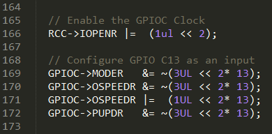
Figure 1 – Configuring the GPIO Pin
Step #2 – Disable interrupts
Once the GPIO pin is configured it is time to start focusing on the actual interrupt configuration. Before doing anything a developer should first disable all interrupts. This ensures that during the setup process a partially configured interrupt doesn’t accidentally fire and throw the system into a chaotic and unknown state.
Step #3 – Clear interrupt flags
With interrupts now disabled the developer no longer has to worry about the setup process being interrupted. However, there could have been interrupts pending prior to the setup process due to start-up state of the system. Clearing out the interrupt flags makes certain that once the interrupt controller is configured and enabled the system won’t immediately jump to an old and expired interrupt request.
Step #4 – Connect pin to interrupt line
The GPIO pin is configured as an input and ready to go but at the moment it isn’t internally connected to anything. In order to trigger an interrupt a developer will need to connect that GPIO pin to the interrupt controller. Each microcontroller does this in a slightly different manner. For an ARM microcontroller, this is done using the system configuration peripherals EXTICFG registers. This requires an additional step of turning on the clock for the system configuration peripheral. Figure 4 show an example of how this can be done for the push button located on GPIO C13 of the STM32Nucleo board.
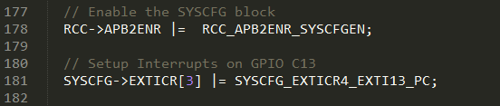
Figure 2 – Connecting GPIO to the Interrupt Controller
Step #5 – Set trigger polarity
The interrupt controller is now connected to the GPIO pin but the controller doesn’t know what should actually trigger the interrupt. Modern microcontrollers have many different options. Interrupts can be level triggered and edge triggered such as rising or falling. The trigger setting will be highly dependent upon the application. For the STM32 Nucleo board, the GPIO has a pull-up that keeps the input at logic 1 unless the button is pressed. The interrupt controller can be setup to trigger on both rising and falling edges. Figure 3 shows how the rising edge trigger is disabled and the falling edge trigger is enabled.
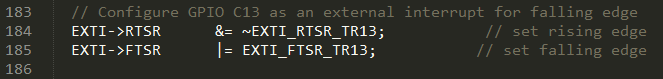
Figure 3 – Setting the falling edge trigger
Step #6 – Set interrupt priority
Modern interrupt controllers are not simple straightforward peripherals. Interrupt controllers provide a wide range of features and capabilities that developers can take advantage of and tune for their own specific application. An interrupt controller can have as many as 256 different interrupts! In the event that two or more interrupts fire at the same time, the controller needs to know which interrupt should be handled first. Setting the interrupt priority can be a simple exercise of just setting the priority bits in the interrupt controller. An example that uses the ARM CMSIS specification can be seen in Figure 4.
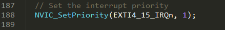
Figure 4 – Setting the interrupt priority
Step #7 – enable interrupts
Enabling interrupts is usually a two-step process. The first step is to examine the interrupt registers and unmask the interrupts that are going to be used by the system. Unmasking the interrupt allows the interrupt controller to respond when that particular interrupt is fired. The second step is then to enable the actual interrupt. Once again enabling interrupts can vary from microcontroller to microcontroller so it is important to have the datasheet open and examine it closely. Figure 5 shows an example of how GPIO C13 on the STM32 Nucleo board is enabled by first unmasking the interrupt and then using CMSIS to enable the interrupt line that is associated with GPIO C13.
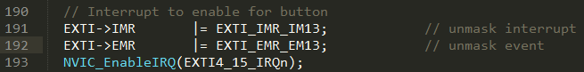
Figure 5 – Enabling the Interrupt
Step #8 – Create interrupt handler
The interrupt controller is now configured! There is just one problem, when an interrupt occurs there is no interrupt handler to respond to the interrupt. The next logical step is to create an interrupt handler. There are a number of ways that this can be done depending not only on the architecture but also on the compiler and IDE. Specifying that a function is an interrupt often uses #pragma or a similar type of compiler intrinsic. When developing on an ARM platform, a developer simply needs to look at the list of interrupts and create a function with the matching pre-specified handler. Figure 6 shows an example of how an interrupt handler would look for GPIO C13.
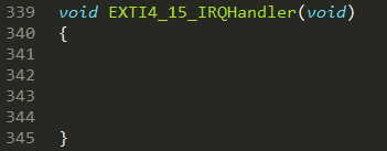
Figure 6 – Empty interrupt handler
Step #9 – Clear interrupt flags in handler
Most microcontrollers require that an interrupt flag be cleared manually by the developer in the interrupt handler. In special cases the interrupt flag is automatically cleared but the datasheet of the microcontroller should be referenced to determine which interrupts behave this way. GPIO interrupts usually fire as a block and upon entering the interrupt a simple check needs to be performed to determine which GPIO line caused the interrupt. The corresponding flag can then be cleared. Figure 7 shows how this can be done.
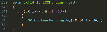
Figure 7 – Clear interrupt flags in handler
Step #10 – Test and debug
Finally after completing all of these steps a developer can now test their code. It is highly improbable that the firmware will run correctly on the first try but having followed each of these steps closely there should only be a minor adjustment required before interrupts are up and running correctly.


