

In the last post, we started to look at how we could design a simple programming adapter for STM32 development boards. We walked through the process necessary to get the schematics completed. In this post, we will examine the the PCB layout along with the BOM and costs necessary to prototype this simple board.
With the schematics completed, the components and nets are pushed into the PCB document literally with the press of a button. There’s not much there. Literally three components with nets that are ready to be routed. I don’t want to spend too much time talking through PCB layout since it’s really beyond the scope of these posts. With that in mind, here are a few bullets on the process that I follow when laying out the board.
- Arrange the components on the blank sheet
- Auto-route to make sure that there is a valid routing solution
- Define the board outline (in this case ~1 inch by 0.75 inches)
- Route any power signals (VCC, etc)
- Set the strategy for return paths and grounds
- Route the signals
- Add polygon fills
- Add copyrights, notes, etc
- Review the layout
- Make any adjustments
- Generate production documents
I will point out that during the components arrangement phase it can be critical to make sure the connectors are in the right direction. The best thing you can do is physically hold and look at the cables. I actually laid this board out and then afterwards found the cable I was going to use. Guess what? Yea, I had P2 rotated 180 degree in the wrong direction! I could have made it work but it turned out that rotating it cleaned up the layout. Just look for yourself at the following top and bottom layers:
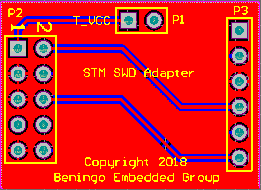
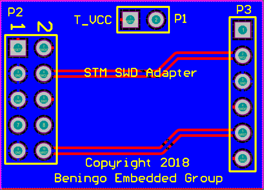
As you can see, using two layers, routing these signals is very easy and was possible without having to add any vias!
One thing I always like to do when designing a board is to look at the generated board on how it is supposed to look in a 3D rendering. When doing this, it’s possible to add in 3D models for the connectors which can then be exported for mechanical engineers to build housings and other work with the electronics model. For this simple board, I didn’t spend the time to add those connector models in. I was still able to look at how the board would look though, which is below:
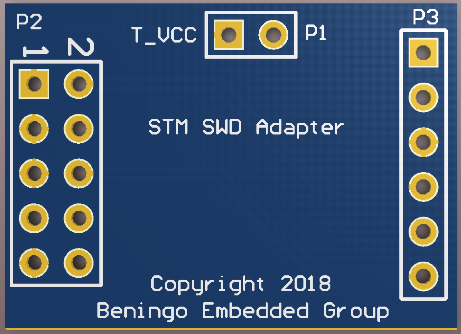
In this model, we are looking at the top layer. On the left, the 10 pin connector would be mounted on the top along with the two pin, male connectors. P3, which is a female connector that connects to the target, will actually be placed on the bottom of the board.
The bill of materials (BOM) for the board is also really simple. I chose the following components for my board:
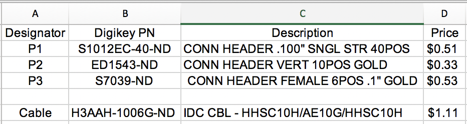
There are several things to note here:
- Component P2 could be very different for developers depending on the cabling that they use on the programmer. I chose to use old school IDC connectors.
- The connector BOM cost is not more than $1.50.
- I added a IDC cable, just in case I didn’t have one, to connect the external programmer to the adapter board.
- The pricing for the PCB is not listed here.
As it turns out, the PCB cost is the largest expense if you are doing a small board run. I poked around and found that for ~$100, including shipping, I could build around 50 boards. This is great if you are planning to manufacture these devices but I really only had interest in building 5. So overall, each adapter will cost me around $25 which is well worth the investment to clean-up the way that I’m interfacing to a development kit.
Could I have done this cheaper? Absolutely! I could have just purchased several $1.11 cables, cut off the connector and then directly soldered the cabling onto the P3 connector. I would still need to add the VCC jumper, but some nice cabling could have been built for probably $5 plus some time at the soldering iron. But let’s be honest, that’s not as fun as laying out a board.
I hope that these two posts have given you some ideas on how you can interface an external programmer to the STM32 development boards. Obviously these ideas could easily be applied to any vendors development boards.


