
Hardware In-Loop Testing
Hardware In-Loop (HIL) testing runs the test case code on the target microcontroller rather than using a mocked software layer to act as the hardware. HIL testing can be extremely useful for verifying that hardware accesses from a HAL are working as expected and even test that all outputs from the system work as expected. The diagram below shows an example what a HIL setup might look like.
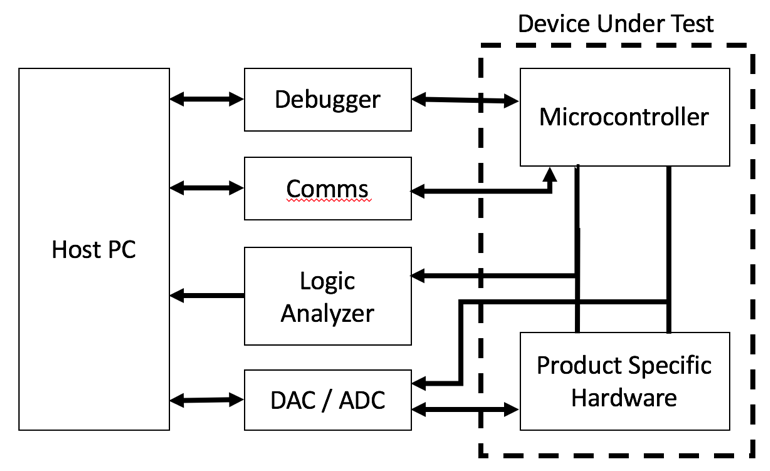
Hardware In-Loop (HIL) testing can contain several different components. First, there is the device under test which is commonly referred to as the DUT. The DUT will information that is critical to access to verify the system is working such as:
• Microcontroller register values
• Pin I/O states
• Communication channels
• Product relates signals from sensors, actuators, etc
Now a developer could go through and manually monitors these signals but that would be a very time consuming process. Instead a developer can build out their HIL test harness to include tools that can automatically sample desired states.
This brings us to our second component, the debugger. The debugger is used by the test controller to load applications and test code onto the target microcontroller but also to control those tests through the debugger communications port. Most modern debuggers act as a virtual communication port and with minimal software a developer can create a test command control channel to manage the microcontroller. The controller can request telemetry, register values and even monitor the software trace and event history.
Next, a developer will normally have a communication channel to talk with the product. For example, if the product is an automotive product then there may be CAN messages that the product responds to that need to be tested. Another example would be a device that has a COMM port. Whatever the communication interface is, there needs to be a tool that can convert that communication to a comm port that the test scripts can control.
Another useful tool to include in the HIL, and one that is very useful for verifying the HAL and configuration tables, is a logic analyzer. Each GPIO pin on the microcontroller can be connected to the logic analyzer and then sampled at a predetermined rate or when events occur in the system. For low-pin count parts, this is straight forward and doesn’t require expensive hardware. However, if the microcontroller being used has a hundred pins or more, logic analyzer hardware could be expensive. Using the same processors development kit, which probably has a header for every pin anyways, can be used as a logic analyzer with a little bit of software.
Developers may also find that their system requires an analog or digital input or that their system outputs an analog or digital signal. In these cases, using an ADC or DAC will give the test harness access to these signals so that they can be recorded while executing the test cases.
Finally, this brings us to the host computer that runs the test suite and must monitor and control the entire testing process. There are several different test harnesses from companies such as LDRA but it is also possible for developers to write their own Python scripts to test and validate their system. In many cases, the direction a team will go will depend upon several factors such as:
• Available budget
• Available time
• Team members available for the project
Identifying at least a minimal test set that covers the basics and user interactions is a must. Integrating hardware in-loop testing can help developers with unit tests, regression testing and functional tests.
Struggling to keep your development skills up to date or facing outdated processes that slow down your team, raise costs, and impact product quality?
Here are 4 ways I can help you:
- Embedded Software Academy: Enhance your skills, streamline your processes, and elevate your architecture. Join my academy for on-demand, hands-on workshops and cutting-edge development resources designed to transform your career and keep you ahead of the curve.
- Consulting Services: Get personalized, expert guidance to streamline your development processes, boost efficiency, and achieve your project goals faster. Partner with us to unlock your team's full potential and drive innovation, ensuring your projects success.
- Team Training and Development: Empower your team with the latest best practices in embedded software. Our expert-led training sessions will equip your team with the skills and knowledge to excel, innovate, and drive your projects to success.
- Customized Design Solutions: Get design and development assistance to enhance efficiency, ensure robust testing, and streamline your development pipeline, driving your projects success.
Take action today to upgrade your skills, optimize your team, and achieve success.


As an automotive technician we are often faced with challenging electronic system faults and I was wondering if there is a good testing method to prove out internal hardware fault when suspected. Would your methods of testing be successful even without the source code as a developer would have access to?
Thanks,
Zach Anderson
Thanks for the comment. These methods are focused on developers who have access to the source. They could probably be modified though to monitor the external behavior of the device. For example, even if you don’t have the source, you could still sniff a CAN or SPI bus and compare the traffic to a known working system. You could monitor voltages on different actuators and sensors, etc and determine if they are going out of range.
I hope this helps!