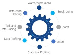
5 Debugging Techniques for the ARM Cortex-M MCU
Debugging embedded software is my least favorite activity but unfortunately a necessary evil. Thankfully recent advances in technology and tool chain innovation has resulted in a plethora of techniques to drastically speed up the debugging process. Let’s examine a few techniques starting from our traditional debugging by break-point through the more advanced instrument trace techniques.

Technique #1 – Traditional break-point debugging
Every developer is familiar with the traditional debugging technique for setting break-points, executing code and then stepping through the code while monitoring registers and variable values. Break-point debugging is a technique that I see used more than any other technique which is disheartening because it is the least efficient and generally yields sub optimal results.
Why are breakpoints used so often? Breakpoints are used so often because they are easy to use, readily accessible and developers are optimistic that breakpoints are the right tool for the job. Break-points have the potential to disrupt the systems real-time performance and can suck a developer into a black hole for endlessly single stepping through code blindly looking for a solution to the problem.
Technique #2 – IDE Value Graphing
Nearly all debuggers and IDE’s now allow a developer to monitor the value stored inside a memory location such as a variable. A developer selects the memory location, the value refresh rate and then starts the debug session. Value monitoring can be very useful but is far more valuable if the data being monitored is tied to a graphical representation. Some IDE’s have the ability to monitor the value built into the IDE while others rely on using an external software.
Graphing the data values in real-time can be extremely useful to discover unexpected changes or to verify that a particular waveform is generated. Take for example a three phase BLDC motor. A developer may want to monitor the current and voltage on each motor leg. A very specific waveform needs to be generated in order to drive the motor. Plotting the voltage and current on each motor leg can allow a developer to visualize what is happening in real-time.
Technique #3 – Reroute printf to SWO
On higher end ARM Cortex-M parts such as the M3/M4, developers are provided with additional debugging capability known as the Serial Wire Viewer (SWV). The SWV comprises the standard serial wire debugger in addition to a Serial Wire Output (SWO). The SWO can be used to do really cool things such as retrieving the program counter, event counter and trace data to name a few. Developers can customize the information that they would like to have transmitted over the SWO.
Many developers’ setup printf in order to get debugging information from their embedded system. Rather than using serial pins on the microcontroller, a developer can use SWO to reroute printf information through the debugger. Using the debugger in this way can save the need for a dedicated serial interface, development time for the UART or USB device and is far more efficient! Overhead that would have originally been used in the application is now off-loaded through the SWO and debugging hardware which saves precious clock cycle that would have otherwise been used by the application code.
Technique #4 – RTOS Tracing
Trying to peer through the veil at what an RTOS is doing can be quite challenging. Developers don’t want to disturb the real-time system performance but still need some method to understand the system. Blinky LEDs have often been the go to trick but more recently trace tools have added an amazing technique to the developers’ toolbox. Free and commercially available RTOS trace tools exist such as TraceX, SystemView and Tracealyzer to name a few.
Trace tools allow a developer to analyze when the RTOS is idle and when each task is entered and exited. Developers can monitor for system exceptions, response time, execution time and many other critical details we need to properly develop an embedded system. The coolest feature available in RTOS trace tools is their ability to visual and graph what is happening in the system. Reviewing and monitoring timing diagrams in real-time or in the recorded log can help give a confidence level that the system is working as expected or help to discover small issues that would have otherwise taken a lot of time to discover.
Technique #5 – Use instruction trace technology (ETM/ETB/ETM)
Sometimes developers face debugging problems that are just at the lowest levels imaginable within the processor. Trace technologies exist that can monitor individual instructions that are executed by the processor. Such low level monitoring can be useful to monitor for branch coverage when testing and validating software. The debugger tools used for instruction trace are different than a developer would use for Serial Wire Viewing and generally cost a little bit more.
Closing Thoughts
Debugging tools and technologies have been rapidly evolving over the past few years especially for higher end microcontrollers. Engineers in general are visual creatures and tool vendors are finding ways to reveal in visually stimulating ways what exactly is happening within a real-time system. Setting up debugging tools can require some upfront setup time but the potential to spend less time debugging and more time designing is well worth the time investment. At a minimum, developers should become familiar with the different debugging tools and capabilities available to them so that when problems arise and the system needs to be debugged, they are aware the right tools exist to get the job done.
What other techniques do you use that can be used to help engineers debug their systems faster and more efficiently?
Struggling to keep your development skills up to date or facing outdated processes that slow down your team, raise costs, and impact product quality?
Here are 4 ways I can help you:
- Embedded Software Academy: Enhance your skills, streamline your processes, and elevate your architecture. Join my academy for on-demand, hands-on workshops and cutting-edge development resources designed to transform your career and keep you ahead of the curve.
- Consulting Services: Get personalized, expert guidance to streamline your development processes, boost efficiency, and achieve your project goals faster. Partner with us to unlock your team's full potential and drive innovation, ensuring your projects success.
- Team Training and Development: Empower your team with the latest best practices in embedded software. Our expert-led training sessions will equip your team with the skills and knowledge to excel, innovate, and drive your projects to success.
- Customized Design Solutions: Get design and development assistance to enhance efficiency, ensure robust testing, and streamline your development pipeline, driving your projects success.
Take action today to upgrade your skills, optimize your team, and achieve success.