Turn a Low Cost Dev Kit into a Programmer in 3 Easy Steps
One of my favorite ARM development tools is my IAR I-Jet debugger. It provides quite a bit of debugging capability not to mention the extra goodies for measuring processor current draw. The only problem is that at $299, an engineer really doesn’t want to purchase a second one for a backup. So in the unfortunate event that it gets fried or more realistically, it gets borrowed, what is one to do if the need arises to program and debug a bug?
One of the super cool features of most low cost development kits these days is that they come with a built-in USB debugger. This debugger is provided so that developers can evaluate a part without having to purchase a more expensive programming tool. The neat part about this is that the on-board debugger can be hijacked to program an external board rather than the on-board microcontroller.
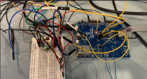
There happened to be a number of spare Freescale Kinetis-L Freedom boards around the office so at a cost of only $12.95 each, the price was definitely right in the event something went wrong. One advantage to using this board is that it does have the PE Micro OpenSDA interface. This is supported by most IDE’s so any compiler environment works well.
STEP 1 – Install a Programmer Header
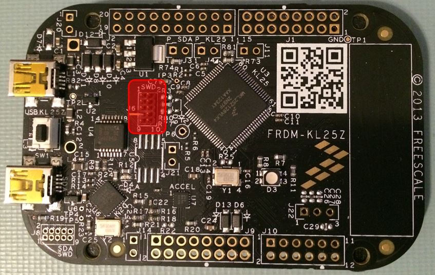
The great part about development kits is that the designers think ahead and usually place a footprint for a SWD connector to be populated so that an external debugger can be used instead of the on-board debugger. This is the perfect place to hi-jack the SWD signals coming from the programmer. In order to do so, simply solder a SWD connector in place as seen in the image below:
STEP 2 – Disconnect the MCU from the SWD Signals
One problem with the on-board programmer is that it is directly tied to the microcontroller that resides on the development kit. If a second processor is attached, additional configuration could be required in the compiler environment or in some cases the programmer may be too confused to be able to program any microcontroller.
The resolution for this is to simply remove the SWD connection from the microcontroller that is part of the development kit. To do this, all that needs to be done is to cut a single trace on the board. This will prevent the programmer from being able to identify the on-board microcontroller. On the Kinetis-L Freedom board, this is done very easily. All that needs to be done is J11, an unpopulated jumper needs to be cut. The great part is that to reconnect the on-board microcontroller all that needs to be done is headers with a jumper can be placed on the board and the board is as good as new! In fact better! J11 can be seen in the image below and as the reader will notice there is a trace between the two pins. Just cut it!

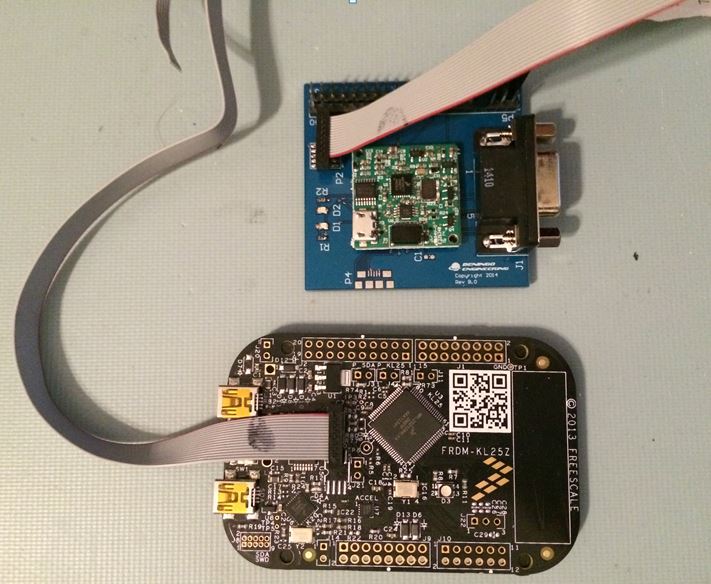
STEP 3 – Connect Target Board with Cable
The only thing left to do at this point is to connect the development kits SWD header with a ribbon cable to the SWD header on the target board. Once this is done, The OpenSDA programmer can be powered through USB, power can be applied to the target and voila! A cheap $12.95 programmer for those times when a quick and dirty, low cost programmer is required!
 Happy Programming Times!
Struggling to keep your development skills up to date or facing outdated processes that slow down your team, raise costs, and impact product quality?
Here are 4 ways I can help you:
- Embedded Software Academy: Enhance your skills, streamline your processes, and elevate your architecture. Join my academy for on-demand, hands-on workshops and cutting-edge development resources designed to transform your career and keep you ahead of the curve.
- Consulting Services: Get personalized, expert guidance to streamline your development processes, boost efficiency, and achieve your project goals faster. Partner with us to unlock your team's full potential and drive innovation, ensuring your projects success.
- Team Training and Development: Empower your team with the latest best practices in embedded software. Our expert-led training sessions will equip your team with the skills and knowledge to excel, innovate, and drive your projects to success.
- Customized Design Solutions: Get design and development assistance to enhance efficiency, ensure robust testing, and streamline your development pipeline, driving your projects success.
Take action today to upgrade your skills, optimize your team, and achieve success.