
Zephyr RTOS: Porting Apps Across Different Boards
During COVID, many embedded developers had a rude awakening when the hardware their products relied on became unavailable. They were forced to port tightly coupled code from one piece of hardware to the next. For many, it was a long and painful process. Unless they built it on Zephyr.
Don’t believe me? Well, let me show you how things could have gone by porting the application we’ve been building for the FRDM-MCXN947 to the FRDM-MCXW71.
In the last post, Zephyr RTOS Sensor API: Unlock On-Board Temperature Sensing, we connected the P3T1755 I3C temperature sensor on the FRDM-MCXN947 to our sensor_blinky application. The application code never touched an I3C register. Everything happened through Zephyr’s sensor API: sensor_sample_fetch(), sensor_channel_get(), and a Devicetree overlay that described the hardware to the build system.
Now we’re going to test whether that abstraction actually holds. We’re porting sensor_blinky to the FRDM-MCXW71, a wireless MCU board with no on-board temperature sensor at all. We’ll wire up an external DHT22, configure it through Devicetree, and see exactly how much application code has to change.
In this post, I’ll walk you through:
- The FRDM-MCXW71 and what makes it different from the FRDM-MCXN947
- Wiring the DHT22 to the Arduino header, and the pin selection constraints that will break your build if you don’t know about them
- Creating the per-board Devicetree overlay and Kconfig fragment
- Why the DHT driver requires
GPIO_ACTIVE_LOW, and what happens when you get it wrong - Building, flashing, and reading live temperature data from the FRDM-MCXW71
Let’s dig in!
Understanding the FRDM-MCXW71
The FRDM-MCXW71 is NXP’s development board for the MCX W716C, a multiprotocol wireless MCU with Bluetooth Low Energy and IEEE 802.15.4 support. We’ll explore those wireless capabilities in a future post. For now, the board gives us something more immediately useful: a completely different hardware platform to test our application’s portability.
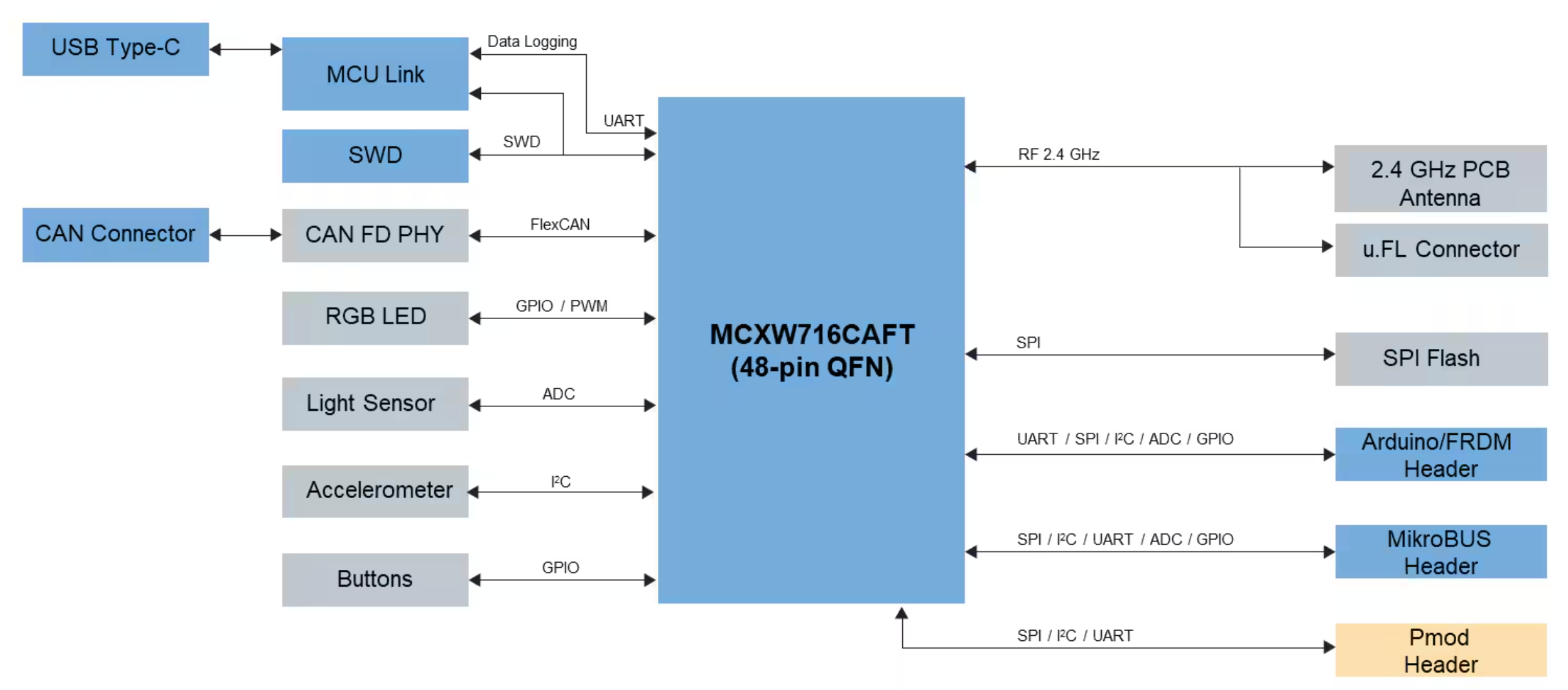
That’s where the MCX W71 differs from the MCX N947. The MCX N947 had a P3T1755 temperature sensor soldered right on the board, wired to the MCU’s I3C bus. The MCX W71 doesn’t have one. The board is built around its radio, not its sensor interfaces. If you want temperature data, you bring your own sensor.
If you’ve worked in embedded product development for any length of time, this shouldn’t surprise you. Not every board ships with the sensors your application needs. Not every project gets to rely on what’s soldered down. This is exactly the situation Zephyr’s Devicetree and per-board overlay mechanism were designed for. You describe your external hardware in a board-specific overlay, and the build system handles the rest.

Free for Zephyr Developers
Get a Free NXP FRDM-MCXA156 Dev Board
NXP is offering 500 free FRDM-MCXA156 boards to embedded developers exploring Zephyr. Limited to 500 boards or available through December 31, 2026, whichever comes first.
Claim Your Free Board →Choosing an External Sensor: The DHT22
For this port, we’re using the DHT22, also sold as the AM2302. It’s a popular, low-cost sensor that measures both temperature and humidity. More importantly for our purposes, it uses a single-wire GPIO protocol. There’s no I2C address to configure, no SPI chip select to manage. You connect the data line to one GPIO pin, add a 10k pull-up resistor, and you’re done.
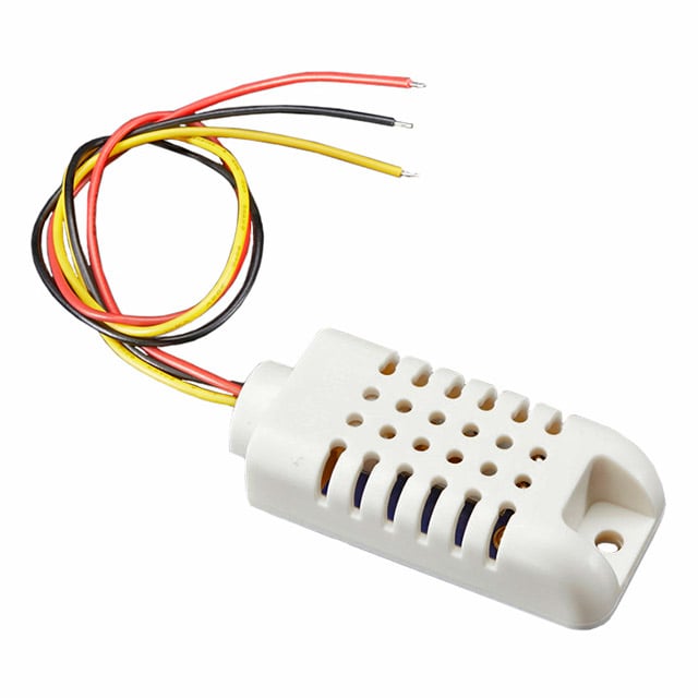
Zephyr has an upstream driver for it under the compatible string aosong,dht. That means no custom driver to write. However, notice that it’s a completely different interface from our P3T1755! You would expect there to be quite a bit of application code to rewrite. We shall see.
If you’re interested, here are the key specs for the DHT22:
- Temperature range: -40C to +80C, +/-0.5C accuracy, 0.1C resolution
- Humidity range: 0-100% RH, +/-2-5% accuracy
- Supply voltage: 3.3V or 5V
- Interface: single-wire open-drain GPIO
- Data format: 40 bits (16-bit humidity + 16-bit temperature + 8-bit checksum)
The DHT22 isn’t a precision instrument, but it’s more than accurate enough to demonstrate Zephyr’s portability story.
It exposes temperature through the same sensor_sample_fetch() / sensor_channel_get() pattern as the P3T1755 did on the FRDM-MCXN947. The sensor API is the common thread across both boards.
Wiring the DHT22 to the FRDM-MCXW71
The DHT22 has four pins. Pin 3 is not connected. The connections are straightforward:
- VCC to 3.3V on the Arduino header (NOT the 5V pin)
- DATA to A0 (PTD1) on the Arduino header
- GND to GND on the Arduino header
There are two details worth calling out before you wire anything up.
The Pull-up Resistor Is Not Optional
The DHT22 uses an open-drain data line. The sensor can only pull the DATA pin LOW; it can’t drive it HIGH. A 10k ohm resistor between VCC and DATA keeps the line HIGH when the sensor is idle. Without it, the DATA line floats and the driver will fail on every read.
Add a 10k pull-up between the 3.3V rail and the DATA pin on your breadboard. That’s the standard configuration, and it’s what the DHT driver expects.
Use 3.3V, Not 5V
The FRDM-MCXW71’s GPIO pins are 3.3V. The DHT22 can run on either 3.3V or 5V, but if you power it at 5V, the DATA line will swing between 0V and 5V, and a 5V high signal driving a 3.3V GPIO input is not a good long-term situation for the MCU. Power it from 3.3V and you stay within spec on both ends.
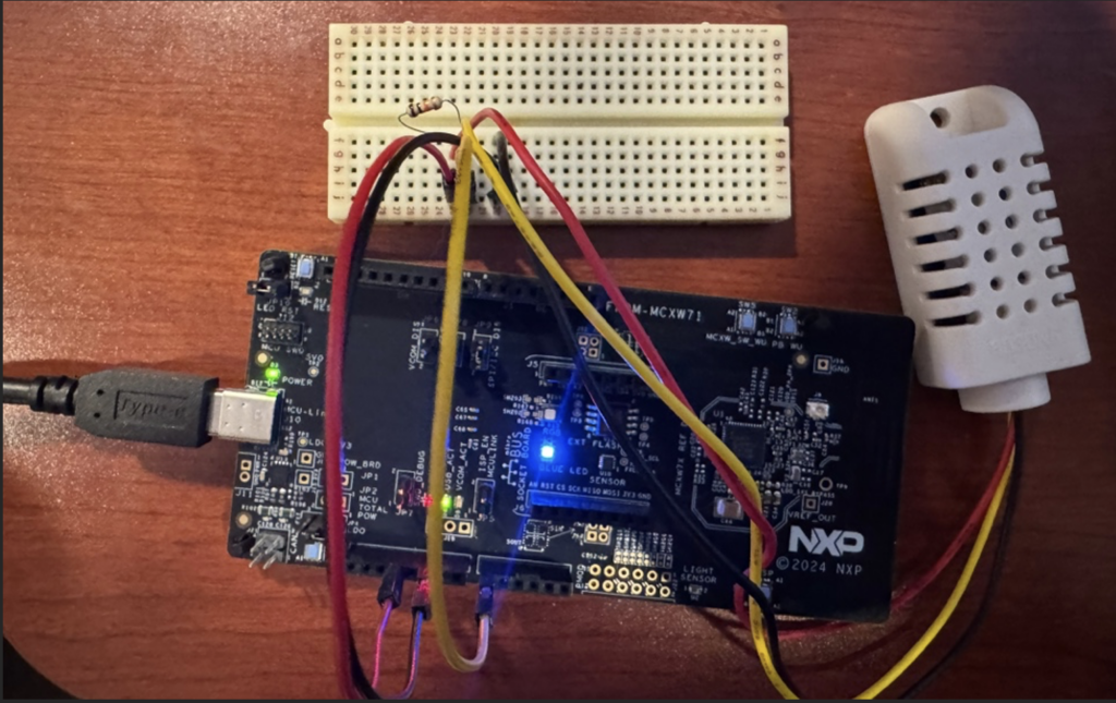
Ultimately, once you’ve connected everything, your setup should look something like the following:
How the DHT22 Protocol Works
Before writing the overlay, it helps to understand what the DHT22 is actually doing on that single wire. The protocol is simple but timing-dependent, and understanding it makes the GPIO_ACTIVE_LOW requirement make sense.
A complete DHT22 read sequence works like this:
- The DATA line idles HIGH, held there by the 10k pull-up resistor.
- The MCU pulls DATA LOW and holds it there for at least 18ms. This is the start signal: it tells the sensor a request is coming.
- The MCU releases DATA (switches to input mode). The pull-up brings the line back HIGH.
- The DHT22 responds by pulling DATA LOW for about 80 microseconds, then releasing it HIGH for about 80 microseconds. This is the sensor’s acknowledgment.
- The sensor then transmits 40 data bits. Each bit starts with a 50-microsecond LOW pulse. A 26-28 microsecond HIGH pulse encodes a 0. A 70-microsecond HIGH pulse encodes a 1.
- After all 40 bits, the sensor pulls DATA LOW briefly and then releases it. The line returns to the idle HIGH state.
Those 40 bits contain 16 bits of humidity data, 16 bits of temperature data, and 8 bits of checksum. The driver verifies the checksum and converts the raw values to the sensor_value format that Zephyr uses for all sensor channels.
The critical point from steps 2 and 3: the MCU must drive DATA LOW for 18ms to start a read. The Zephyr DHT driver does this by asserting the GPIO pin to its logical active state. For that to produce a LOW signal on the wire, the pin must be configured as GPIO_ACTIVE_LOW.
Navigating the Arduino Header Pin Constraints
The FRDM-MCXW71’s Arduino header looks standard at first glance, but several pins have hardware constraints that aren’t obvious from looking at the connector. This is the part that causes problems if you don’t know what to look for.
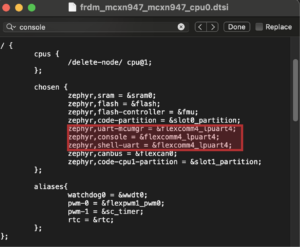
D0-D3 Are Muxed for BLE UART and CAN0
Pins D0 through D3 are muxed for the BLE UART and the CAN0 peripheral in the board’s default Devicetree. D3 in particular is PTC5, which is CAN0_RX. The flexcan0 node in the board’s DTS file has status = "okay" by default, which means the CAN driver initializes at boot and claims that pin. If you try to use D3 as a general GPIO, the driver will appear to configure correctly, but the CAN peripheral holds the pin mux and the signal won’t behave as GPIO.
The safest approach is to avoid D0 through D3 entirely unless you specifically need those peripherals and are willing to disable the conflicting drivers.
A3 (PTA4) Is the ISP Boot Pin
This one is subtle, and it’s worth understanding the failure mode in detail because it looks like a completely dead board.
PTA4, which maps to Arduino A3, is the FRDM-MCXW71’s ISP (In-System Programming) entry pin. At power-up, the boot ROM samples PTA4. If it detects a LOW level, it enters serial ISP mode instead of running user firmware.
The DHT22 DATA line is briefly LOW during sensor power-on initialization, for approximately 20ms right after the board powers up. That’s long enough for the boot ROM to sample it. If you wire the DHT22 to A3, the board will enter ISP mode on every power cycle, and your firmware will never run. The LED won’t blink. The shell won’t respond. Nothing will work.
The failure mode is frustrating because the board isn’t defective and the firmware compiled correctly. The problem is entirely the pin choice.
A0 (PTD1) Is the Right Pin
Arduino A0 maps to PTD1. It has no boot-mode function, and no conflicting peripheral is enabled in the default board configuration. It’s the correct pin for the DHT22 DATA line on this board.
Creating the Per-Board Devicetree Overlay
Zephyr’s per-board override mechanism uses a boards/ directory inside your application. When you build for a specific board, Zephyr automatically picks up any overlay or Kconfig fragment that matches the board name. You don’t need to specify these files manually on the command line.
For the FRDM-MCXW71, create this file in your application:
boards/frdm_mcxw71_mcxw716c.overlayThe filename matches the board target used in the west build command. Here’s the content:
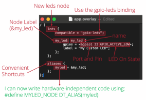
/ {
    dht22: dht22 {
        compatible = "aosong,dht";
        dio-gpios = <&gpiod 1 (GPIO_PULL_UP | GPIO_ACTIVE_LOW)>;
        dht22;
        status = "okay";
    };

    aliases {
        temp-sensor = &dht22;
    };
};

&gpiod {
    status = "okay";
};Let’s walk through each part of this overlay.
compatible = "aosong,dht" tells Zephyr which driver to bind to this node. The build system looks up this string in the driver registry, finds the DHT driver, and compiles it in.
dio-gpios = <&gpiod 1 (GPIO_PULL_UP | GPIO_ACTIVE_LOW)> specifies the GPIO pin. gpiod is the GPIO port, 1 is the pin number within that port (PTD1 = port D, pin 1), GPIO_PULL_UP enables the internal pull-up (your external 10k pull-up makes this belt-and-suspenders, but it doesn’t hurt), and GPIO_ACTIVE_LOW is critical.
dht22; is a boolean property that tells the driver this is a DHT22 specifically (as opposed to a DHT11, which uses slightly different timing).
The aliases block maps the generic name temp-sensor to the dht22 node. The application code only ever sees temp-sensor. Adding support for a new board requires only a new overlay pointing the alias at the right node. Nothing in the application changes.
The &gpiod node reference at the bottom enables GPIOD in the Devicetree. The FRDM-MCXW71’s board DTS doesn’t enable gpiod by default, so this overlay line is required. Without it, the build will fail with a node reference error.
Adding the Alias to the MCXN947 Overlay
The FRDM-MCXN947 also needs a temp-sensor alias so the application can reference the same generic name on both boards. The P3T1755 is defined in the board’s built-in DTS, not your application overlay. Your overlay only needs to add the alias pointing to it.
Create or update boards/frdm_mcxn947_mcxn947_cpu0.overlay:
/ {
    aliases {
        temp-sensor = &p3t1755;
    };
};That is the entire overlay for the MCXN947. The sensor node already exists in the board DTS. You are just giving it the generic name the application expects.
Understanding GPIO_ACTIVE_LOW
GPIO_ACTIVE_LOW is the detail that trips up almost everyone the first time they use the DHT driver. It’s worth understanding exactly why it’s required.
The DHT22 protocol starts with the MCU pulling the DATA line LOW for at least 18ms. That LOW pulse is the start signal. Without it, the sensor never responds.
The Zephyr DHT driver generates this signal using the pin’s logical active/inactive states. Between measurements, it holds the pin at OUTPUT_INACTIVE. At the start of a measurement, it sets the pin to logical active (set(true)), holds for 18ms, then releases the pin to input mode.
For that sequence to produce a LOW pulse as the start signal, logical active must correspond to electrical LOW. That’s what GPIO_ACTIVE_LOW specifies: the active (true) state corresponds to a LOW voltage on the wire.
With GPIO_ACTIVE_LOW, the signal behavior is:
OUTPUT_INACTIVE= electrical HIGH (line idles high, correct idle state for DHT22)set(true)= electrical LOW (the 18ms start signal the sensor expects)- Release to input = pull-up brings line back HIGH, sensor responds
With GPIO_ACTIVE_HIGH, the behavior inverts:
OUTPUT_INACTIVE= electrical LOW (line is always pulled LOW at idle, wrong)set(true)= electrical HIGH (not a valid start signal, sensor ignores it)- Sensor never receives a valid start pulse, never responds
If you use GPIO_ACTIVE_HIGH, the device will appear in the device list as READY, but every call to sensor_sample_fetch() will return -EIO (-5). The sensor is physically present and wired correctly. The driver is initialized. But the signal polarity is inverted, so the start handshake never succeeds.
If you see -EIO on every fetch and the sensor appears ready, the first thing to check is the GPIO_ACTIVE_LOW flag in your overlay.
Adding the Per-Board Kconfig Fragment
Alongside the overlay, create a matching Kconfig fragment:
boards/frdm_mcxw71_mcxw716c.confWith this content:
CONFIG_GPIO=y
CONFIG_DHT=y
CONFIG_DHT_LOCK_IRQS=yCONFIG_DHT=y enables the DHT driver itself. Without it, the driver code never compiles in, and the aosong,dht compatible string won’t resolve to anything.
CONFIG_DHT_LOCK_IRQS=y is important. The DHT22 protocol is timing-sensitive. The driver needs to measure pulse widths in the tens-of-microseconds range to decode the 40 data bits correctly. If an interrupt fires during a measurement and takes even a few microseconds to service, it can stretch a timing window enough to corrupt the reading.
Locking interrupts during the measurement prevents that from happening. On a preemptive RTOS like Zephyr, this is not optional if you want reliable readings under any real workload. Without it, measurements will fail intermittently and in ways that are difficult to reproduce.
Writing Portable Application Code with DT_ALIAS
Here’s what this whole setup is building toward: the application code is genuinely identical between the two boards. Not nearly the same: byte-for-byte identical.
The device pointer in main.c is a single line:
static const struct device *sensor = DEVICE_DT_GET(DT_ALIAS(temp_sensor));There are no #if blocks, no compatible strings, no sensor names anywhere in the application. temp_sensor is a generic alias defined in each board’s overlay. The build system resolves it to whichever sensor node that board’s overlay points to. On the FRDM-MCXN947, temp-sensor = &p3t1755. On the FRDM-MCXW71, temp-sensor = &dht22. The C code never knows or cares which one it is.
This is what DT_ALIAS is designed for. The alias lives in the Devicetree, which is board-level configuration. The application lives above that. The two never touch.
One important detail: if you build for a board whose overlay does not define a temp-sensor alias, the build fails at compile time. This is intentional. A missing alias is a configuration error, and catching it at build time is far better than a silent runtime failure.
The actual sensor reads are identical on both boards:
sensor_sample_fetch(sensor);
sensor_channel_get(sensor, SENSOR_CHAN_AMBIENT_TEMP, &temp);The same channel constant. The same two function calls. The same struct sensor_value result. Whether the driver underneath is talking I3C to a P3T1755 or toggling a GPIO to read a DHT22, the application code sees no difference.
The main loop and the shell command both use the same pattern. Here’s the main loop’s temperature read:
if (sensor_sample_fetch(sensor) == 0) {
sensor_channel_get(sensor, SENSOR_CHAN_AMBIENT_TEMP, &temp);
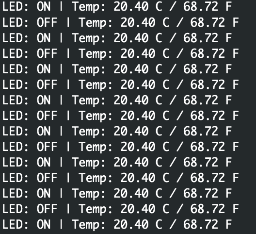
printk("LED: %s | Temp: %s%d.%06d Cn",
led_state ? "ON" : "OFF",
sv_neg(&temp) ? "-" : "",
sv_abs1(&temp), sv_abs2(&temp));
}The sensor_value struct uses two fields: val1 holds the integer part and val2 holds the fractional part in millionths. A reading of 20.9 degrees comes back as val1=20, val2=900000. The helper functions sv_neg(), sv_abs1(), and sv_abs2() handle the edge case where a negative fractional value (like -0.5 degrees) would need the sign handled separately from the integer part.
The only files that changed between the FRDM-MCXN947 and FRDM-MCXW71 builds are the board-specific files: the two overlays (one per board, each defining the temp-sensor alias) and the MCXW71 Kconfig fragment. The prj.conf and main.c are untouched.
Building and Flashing for the MCXW71
Building for the FRDM-MCXW71 uses the same west command pattern as any other board:
west build -b frdm_mcxw71/mcxw716c -p always /path/to/sensor_blinky
west flashThe -p always flag forces a pristine build, which is a good habit when switching between board targets. Zephyr’s build caches some configuration per-board, and a pristine build ensures you’re not accidentally picking up configuration from a previous FRDM-MCXN947 build.
You might be wondering about the board suffix. frdm_mcxw71/mcxw716c specifies the board variant, where mcxw716c identifies the specific MCU variant on the FRDM-MCXW71. The slash notation is Zephyr’s way of targeting a specific hardware configuration when a board supports multiple MCU variants.
Verifying the Results
With the DHT22 wired to A0, the firmware running, and a serial terminal connected at 115200 baud, the main loop prints temperature data alongside the LED state:
The shell temp command also works directly:
uart:~$ temp
Temperature: 20.900000 CBoth paths, the main loop and the shell command, use the same sensor API calls. The code that read temperature from an I3C bus on the MCXN947 is reading from a single-wire GPIO sensor on the FRDM-MCXW71, and producing identical output.
As you can see, the portability story holds. The sensor API abstraction is real, not theoretical.
What Changed and What Didn’t
Now that we’ve seen the full setup, it’s worth being explicit about exactly what the port required.
What changed:
boards/frdm_mcxw71_mcxw716c.overlay– describes the DHT22 hardware and maps thetemp-sensoralias to&dht22boards/frdm_mcxw71_mcxw716c.conf– enables the DHT driver and interrupt locking- Physical hardware – external DHT22 and pull-up resistor instead of on-board P3T1755
What was added for the MCXN947 side:
boards/frdm_mcxn947_mcxn947_cpu0.overlay– maps thetemp-sensoralias to&p3t1755
What didn’t change:
src/main.c– no sensor names, no#ifblocks, identical between both buildsprj.conf– the base Kconfig configuration is unchanged- The sensor API calls –
sensor_sample_fetch()andsensor_channel_get()are the same on both boards
The per-board overlay and Kconfig fragment are the entire scope of the code change. Everything else, the build system, the application logic, the sensor API, the shell commands, carries over automatically.
That’s the Zephyr portability model in practice. The Devicetree and its overlay mechanism absorb the differences between hardware. The sensor API provides a stable interface above those differences. The result is that you can move an application from one target to another by describing the new hardware, not by rewriting the application.
Your Next Steps
At this point, you should have a working DHT22 sensor on the FRDM-MCXW71, reading temperature through the same Zephyr sensor API that previously talked to the P3T1755 on the FRDM-MCXN947. The per-board overlays handled all the board-specific differences. The application code is literally unchanged: the same main.c, byte for byte, built for both targets.
Here are a few steps I’d recommend to go deeper:
- Replicate the build and verify you get a temperature reading. Pay particular attention to
GPIO_ACTIVE_LOWin the overlay. Ifsensor_sample_fetch()returns-EIOon every call, that’s the first thing to check. - Try reading humidity in addition to temperature. The DHT22 reports both, and the driver supports
SENSOR_CHAN_HUMIDITYthrough the same API. Add a secondsensor_channel_get()call and print both values. - Browse the Zephyr repo at
dts/bindings/sensor/to explore the full range of supported sensors. For any sensor with an upstream binding and driver, the integration path is: write an overlay, add a Kconfig line, connect the hardware.
In the next post, we’ll build on this setup and add BLE telemetry to the FRDM-MCXW71. The sensor application will start broadcasting live temperature readings over Bluetooth, which opens up a whole new set of possibilities for wireless sensor nodes.
Additional Resources
- Blog: Introduction to the NXP MCX N FRDM Board
- Blog: Getting Started with Zephyr RTOS
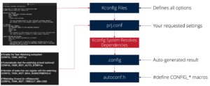
- Blog: How to Configure Zephyr RTOS: A Practical Guide to West, Kconfig, proj.conf
- Blog: FreeRTOS to Zephyr Migration: A Step-by-Step Guide for Embedded Developers
- Blog: Mastering the Zephyr RTOS Devicetree and Overlays
- Blog: Zephyr RTOS Sensor API: Unlock On-Board Temperature Sensing
- Free Training: Getting Started with MCUXpresso for Visual Studio Code
- Free Webinar: Getting Started with the MCUXpresso SDK for NXP MCUs
- Free Webinar: Migrating from FreeRTOS to Zephyr RTOS
- Free Webinar: Mastering Zephyr Devicetree
Don’t miss the rest of this series. Sign up for my Embedded Bytes newsletter to get the latest posts, insights, and hands-on tips delivered straight to your inbox.
Struggling to keep your development skills up to date or facing outdated processes that slow down your team, raise costs, and impact product quality?
Here are 4 ways I can help you:
- Embedded Software Academy: Enhance your skills, streamline your processes, and elevate your architecture. Join my academy for on-demand, hands-on workshops and cutting-edge development resources designed to transform your career and keep you ahead of the curve.
- Consulting Services: Get personalized, expert guidance to streamline your development processes, boost efficiency, and achieve your project goals faster. Partner with us to unlock your team's full potential and drive innovation, ensuring your projects success.
- Team Training and Development: Empower your team with the latest best practices in embedded software. Our expert-led training sessions will equip your team with the skills and knowledge to excel, innovate, and drive your projects to success.
- Customized Design Solutions: Get design and development assistance to enhance efficiency, ensure robust testing, and streamline your development pipeline, driving your projects success.
Take action today to upgrade your skills, optimize your team, and achieve success.