

Mastering the Zephyr RTOS Devicetree and Overlays
If you’ve been building embedded systems for a while, you’ve probably configured hardware the “traditional” way. Diving into header files, tweaking HAL initialization code, and scattering pin settings across your project. It works, but it doesn’t scale.
Zephyr takes a very different approach.
Instead of wiring up your peripherals in C, Zephyr gives you a centralized, machine-readable description of your hardware: the Devicetree. It defines what hardware exists, how it’s connected, and which peripheral instances your firmware should use.
At first, the syntax can feel foreign, especially if you’re coming from FreeRTOS, which has no conceptual equivalent. But once you understand how the Devicetree fits into Zephyr’s build system, you’ll discover it unlocks cleaner code, better reuse, and dramatically easier board customization.
That’s where overlays come in. Overlays let you adapt Zephyr to your custom hardware without rewriting drivers or forking board definitions, something every product team needs sooner or later.
In this post, I’ll walk you through:
- What the Devicetree is and why Zephyr uses it
- How DTS and DTSI files work on a real board (using the FRDM-MCXN947 as an example)
- How the Devicetree flows through the build and configuration system
- How to write overlays that customize pinmux, peripherals, and device instances for your hardware
By the end, the Devicetree won’t feel mysterious anymore; it will feel like a superpower.
Let’s dig in!
What is a Devicetree?
The Devicetree is a data structure that is used to describe your hardware. Yes, it’s that simple.
Instead of scattering peripheral setup across init functions, HAL calls, and board-specific code, Zephyr consolidates that information in a single place.
The Devicetree is made up of at least three files that are used to describe your hardware:
- .dts
- .dtsi
- .overlay
Let’s walk through what each of these files is, what they do, and how to interpret them.
The Devicetree Source File (.dts)
The Devicetree Source file, .dts, is the top-level Devicetree description for a board. It represents the root node, the top of the tree, for your hardware description.
The root node is represented by a /. This is the top of the hardware hierarchy. Anything that is placed under / becomes a top-level property of the board.
For example, take a look at the .dts file for the FRDM-MCXN947 development board frdm_mcxn947_mcxn947_cpu0.dts.
If you peek in that file, you’ll find the following code:
#include "frdm_mcxn947_mcxn947_cpu0.dtsi"

/ {
     model = "NXP FRDM_N94 board";
     compatible = "nxp,mcxn947", "nxp,mcx";
};You can see that the root node is defined by /{ }; . Then, some structured data describes the hardware. The model is just a human-readable description of the board. The critical information is the compatible line.
Compatible is telling Zephyr that this board is compatible with any drivers and bindings compatible with nxp, mcxn947. It’s also saying that it’s compatible with any generic drivers and bindings that support the nxp,mcx family.
Note: A Devicetree binding is the YAML schema that tells Zephyr how to interpret a node and which driver it should use.
Now, you might be thinking, “Okay, this is great, but where are all the hardware definitions?”
That’s where the #include “frdm_mcxn947_mcxn947_cpu0.dtsi file comes in!
The Devicetree Source Include File (.dtsi)
The Devicetree Source Include file, .dtsi, is the System on Chip (SoC) hardware description. That is, it’s the hardware description file for all the peripherals, memory, and other stuff that’s inside your microcontroller. It’s not necessarily limited though to just the microcontroller. It can also be the entire development or production board, including external devices, as we’ll see shortly.
The .dtsi files are “inheritable”. At compile time, the preprocessor copies and pastes them into the .dts file if they are included with #include.
Let’s take a look at the frdm_mcxn947_mcxn947_cpu0.dtsi file.
There are several points to note here.
First, there are more #includes! If you follow these down the tree, you’ll find the following:
- frdm_mcxn947.dtsi defines peripheral settings and on-board devices like the LEDs and the pins they are on.
- frdm_mcxn947-pinctrl.dtsi defines pin settings.
- Etc
Again, these .dtsi files are designed to be inheritable so that you can make them modular.
You might be wondering what the syntax for these files actually mean. We’ll discuss that shortly. Before we do, I want to discuss the third and final Devicetree file you need to be aware of, the application overlay file.
The Devicetree Application Overlay File (.overlay)
When you start writing Zephyr applications, you’ll quickly discover that the default Devicetrees don’t always match your hardware needs.
Maybe you’re adding a new sensor or using a different UART. It could be you wired an LED to a pin the board file has configured for an entirely different purpose.
You could modify the vendor’s Devicetree files, but that’s a terrible idea.
Those files are shared by everyone and maintained by the Zephyr project. Changing them creates long-term maintenance pain.
That’s where the application overlay (app.overlay) comes in.
The overlay lets you extend or override parts of the Devicetree without touching the underlying board files. It gives you a clean, isolated way to describe hardware changes that apply only to your project.
You could have three projects all using the same Devicetree files, but with different app.overlay files to configure the Devicetree for the specific application needs.
In practice, overlays are how you make the Devicetree your own. You layer your application’s needs on top of the SoC and board description.
How Zephyr RTOS Builds and Uses the Devicetree
Now that we’ve looked at the different Devicetree files, the natural question is: How does Zephyr actually use all of this information?
Figure 1 below shows the general flow of how all these files are brought together so that you can use the Devicetree in your application.

When you compile your application, the first thing that happens is that your boards .dts file is read. As we saw earlier, this file has #includes that the pre-processor will “copy and paste” to create the final Devicetree file.
All .dts and the app.overlay file are then passed into the Devicetree compiler to create the final generated Devicetree. The final Devicetree file is a header file named devicetree_generated.h. It contains all the macros necessary for your application to interact with the device tree.
These include macros such as GPIO_DT_SPC_GET, which retrieves the device tree node specification passed to it.
For example, if you want to manipulate an LED, you must first create an LED object using the Devicetree as follows:
#define LED0_NODE DT_ALIAS(led0)

static const struct gpio_dt_spec led = GPIO_DT_SPEC_GET(LED0_NODE, gpios);LED0_NODE is the Devicetree node identifier. It resolves the Devicetree node that represents the LED.
The GPIO_DT_SPEC_GET then looks inside that node and retrieves the gpios properties like the GPIO port, pin number, etc. This information is then packaged into the led object in a structure that Zephyr understands.
Then we can use the led in our application by running code like:
gpio_pin_toggle_dt(&led);The gpio API’s know how to work with the gpio_dt_spec struct and if we ran the code, we’d see our LED toggling!
Does our application know what pin, port, etc the LED is on? Nope. It doesn’t care! The Devicetree abstracted those details away. That means we could just as easily run the application on the FRDM-MCXN947 or run it on a different board!
Our application code is decoupled from our hardware!
Adding an LED with an Application Overlay
We’ve talked a lot about what the Devicetree is, the files involved, and how it’s brought into our application. Let’s look at an example and go through the syntax.
Goals and Hardware Setup
In this example, we are going to use the samples/basic/blinky example to:
- Blink the default red LED
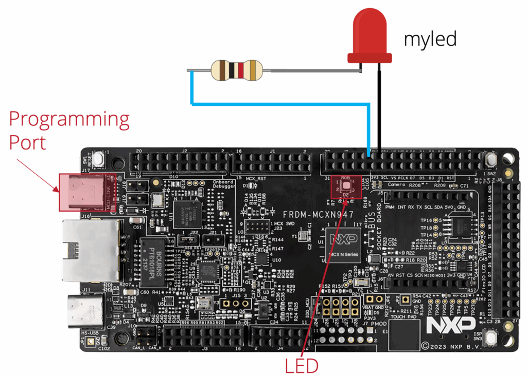
- Blink an added LED on GPIO1, pin 22
- Build the project successfully
- Deploy the project with west
You may be saying that the board already has several LEDs, why add another? Because it’ll help you understand the Devicetree and how to use overlays.
Figure 2 is how I configured my hardware.
Writing Your app.overlay
I’m going to assume that you’ve been following this series and know how to either import an example or know how to copy and paste blinky and open it in VS Code. You should find that your initial blinky directory looks something like the following:
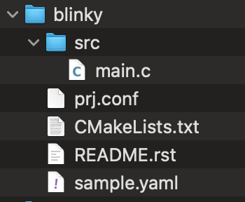
You’ll probably find, as I did, that the blinky sample doesn’t have an app.overlay file by default. You just add a new file and give it that name.
Once you do that, you can add the following code to your overlay:
/ {
    leds {
        compatible = "gpio-leds";

        my_led: my_led {
            gpios = <&gpio1 22 GPIO_ACTIVE_LOW>;
            label = "My Custom LED";
        };
    };

    aliases {
        myled = &my_led;
    };
};This overlay is doing two things: adding a custom LED, and creating an alias so your application can reference it cleanly.
At the top, the leds node defines a brand-new LED that wasn’t part of the default board configuration. The compatible = “gpio-leds” entry tells Zephyr this node contains GPIO-driven LEDs. GPIO driven LEDs is a Zephyr standard API, so we are telling Zephyr this is the driver to bind to.
Inside the leds node, the my_led node declares an LED on GPIO1 pin 22, configured as active-low, and gives it a readable label. That’s all Zephyr needs to generate the correct pin configuration at build time.
Finally, the aliases section creates an alias named myled that points to the new LED. Aliases are incredibly useful because they let you reference hardware symbolically from application code:
DEVICE_DT_GET(DT_ALIAS(myled));No port. No pin. No wiring details in the code.
This small overlay shows the real power of Zephyr’s Devicetree system: you describe your hardware once, in a structured way, and the rest of your firmware follows automatically.
Note: Below is an annotated description of everything that is going on in our overlay file:

Your Next Steps
At this point, you’ve seen what the Devicetree is, how the .dts and .dtsi files fit together, and how an app.overlay lets you adapt Zephyr to your own hardware without touching vendor files.
It’s easy to read about this and think “got it,” but Devicetree really clicks when you start changing it on a real project.
- Browse Zephyr’s Devicetree documentation.
- Trace your board’s Devicetree stack
Open your board’s .dts file and follow the #include chain into the SoC and board .dtsi files. Make a quick sketch of where the CPU, memory, GPIO, UART, and LEDs are defined. This alone will give you a much clearer picture of how Zephyr sees your hardware. - Add or move one peripheral with an overlay
Start with something simple, like the LED example we just looked at. Try to configure a USART or add a sensor.
The goal isn’t to memorize every Devicetree macro or its syntax, after all, you can always read the Devicetree Docs.
The goal is to start thinking of Devicetree as an architectural tool that lets you keep hardware details out of your application and drivers, so your firmware can follow your hardware without a rewrite.
In the next post, we’ll discuss Zephyr RTOS: Leveraging an Ecosystem of Middleware and Drivers.
Additional Resources
- Blog – Introduction to the NXP MCX N FRDM Board
- Blog – Getting Started with Zephyr RTOS
- Blog – How to Configure Zephyr RTOS: A Practical Guide to West, Kconfig, proj.conf
- Blog – FreeRTOS to Zephyr Migration: A Step-by-Step Guide for Embedded Developers
- Free Training – Getting Started with MCUXpresso for Visual Studio Code
- Free Webinar – Getting Started with the MCUXpresso SDK for NXP MCUs
- Free Webinar – Migrating from FreeRTOS to Zephyr RTOS
👉 Don’t miss the rest of this series. Sign up for my Embedded Bytes newsletter to get the latest posts, insights, and hands-on tips delivered straight to your inbox.
Struggling to keep your development skills up to date or facing outdated processes that slow down your team, raise costs, and impact product quality?
Here are 4 ways I can help you:
- Embedded Software Academy: Enhance your skills, streamline your processes, and elevate your architecture. Join my academy for on-demand, hands-on workshops and cutting-edge development resources designed to transform your career and keep you ahead of the curve.
- Consulting Services: Get personalized, expert guidance to streamline your development processes, boost efficiency, and achieve your project goals faster. Partner with us to unlock your team's full potential and drive innovation, ensuring your projects success.
- Team Training and Development: Empower your team with the latest best practices in embedded software. Our expert-led training sessions will equip your team with the skills and knowledge to excel, innovate, and drive your projects to success.
- Customized Design Solutions: Get design and development assistance to enhance efficiency, ensure robust testing, and streamline your development pipeline, driving your projects success.
Take action today to upgrade your skills, optimize your team, and achieve success.