
Zephyr RTOS Sensor API: Unlock On-Board Temperature Sensing
Every embedded product eventually needs to sense something. Temperature. Vibration. Pressure. Humidity. And every time, the story plays out the same way: find a sensor, read the datasheet, write register-level code, debug the bus, and hope the next sensor swap doesn’t break everything. The Zephyr RTOS sensor API was designed to solve exactly this problem.
The Zephyr RTOS sensor API changes that story entirely.
Instead of writing custom code for every sensor, the Zephyr RTOS sensor API provides a standardized interface. One function to fetch a sample. One function to read the result. The sensor driver handles the rest, and the application never needs to know what bus, register, or data format is involved.
In this post, I’ll walk you through:
- How the Zephyr RTOS sensor API works and why it matters for portable firmware
- Adding the on-board P3T1755 temperature sensor to our blinky project using a Devicetree overlay
- Enabling the sensor subsystem through Kconfig
- Reading live temperature data using
sensor_sample_fetch()andsensor_channel_get()
We’ll do all of this on the FRDM-MCXN947 using a sensor that’s already soldered on the board. No shields. No breakout boards. Just the FRDM board you already have.
Let’s dig in!
How the Zephyr RTOS Sensor API Works
Before we add a sensor to our project, it’s a good idea to understand the Zephyr RTOS Sensor API and how it works.
For most embedded developers, when you want to access a sensor, you make a direct call to the sensor interface and gain access to that sensor’s data. There’s no standardization. Every sensor interface is different.
That means for most developers, adding a new sensor results in writing I2C or SPI transactions by hand, parsing raw register values, and converting binary data into meaningful units. When the sensor changes, the application code breaks.
The Zephyr RTOS sensor API eliminates that work by standardizing the interface and splitting sensor access into three layers:
- Devicetree — Describes the physical hardware: which sensor is on which bus, at what address. This is where you declare a sensor node and tell the build system it exists.
- Sensor driver — A kernel module matched to the Devicetree node by its compatible string. The driver knows how to communicate with the hardware via register reads, writes, bus transactions, and data conversions.
- Sensor API — The application-facing interface. Two functions are all you need: one to trigger a measurement, one to retrieve the result. The API talks to the driver. The driver talks to the hardware. Your application stays clean.
In Zephyr RTOS: Leveraging an Ecosystem of Drivers and Middleware, we saw how the Devicetree, drivers, bindings, and Kconfig work together to describe your hardware setup to Zephyr.
From the application’s perspective, the Zephyr RTOS sensor API is interesting because it uses a simple pattern regardless of whether the sensor is a temperature IC, an accelerometer, or a pressure transducer. The workflow looks like this:
- Fetch —
sensor_sample_fetch()tells the driver to read the hardware - Get —
sensor_channel_get()retrieves the result for a specific channel
That’s it. Whether you’re reading temperature from an NXP P3T1755, acceleration from a Bosch BMI270, or pressure from a Bosch BMP388, the pattern is identical.
Now, we don’t want to get too far ahead of ourselves, but here is what a basic Zephyr RTOS sensor API read looks like in code:
const struct device *sensor = DEVICE_DT_GET_ANY(nxp_p3t1755);
struct sensor_value temp;

sensor_sample_fetch(sensor);
sensor_channel_get(sensor, SENSOR_CHAN_AMBIENT_TEMP, &temp);

printk("Temperature: %d.%06d Cn", temp.val1, temp.val2);sensor_sample_fetch() tells the driver to read the hardware. sensor_channel_get() retrieves the result for a specific channel.
In this case, SENSOR_CHAN_AMBIENT_TEMP. Zephyr RTOS defines a wide range of channels in sensors.h like SENSOR_CHAN_ACCEL_X, SENSOR_CHAN_PRESS, SENSOR_CHAN_HUMIDITY, and dozens more. You can find a full list in the Zephyr sensor documentation.
Once the get API has been called for the desired sensor and channel, the result comes back in the struct sensor_value, variable temp, with two fields:
val1for the integer portionval2for the fractional portion in millionths
So a temperature of 24.5625°C comes back as val1 = 24 and val2 = 562500.
Notice that the application never touches a register. It never needs to know the I2C address, the data format, or even what bus the sensor is on. Swap the sensor, change the board, move from I2C to I3C, and the application code stays the same.

Free for Zephyr Developers
Get a Free NXP FRDM-MCXA156 Dev Board
NXP is offering 500 free FRDM-MCXA156 boards to embedded developers exploring Zephyr. Limited to 500 boards or available through December 31, 2026, whichever comes first.
Claim Your Free Board →The Hardware: P3T1755 on the I3C Bus
The FRDM-MCXN947 has a P3T1755 digital temperature sensor soldered directly on the board. No external wiring needed.
Here’s what makes it useful:
- Resolution: 0.0625°C (12-bit)
- Range: -40°C to +125°C
- Accuracy: ±0.5°C
- Bus: I3C (also backward compatible with I2C)
- Zephyr driver: Available in Zephyr 4.1 as
nxp,p3t1755
The sensor connects to the I3C1 bus on the MCXN947 as shown in Figure 1.
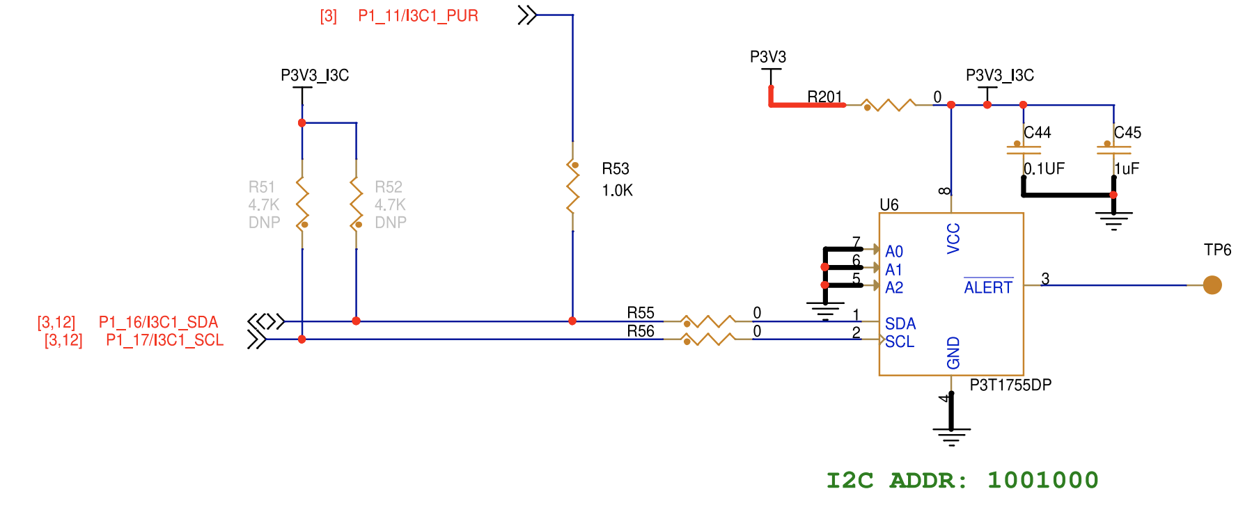
Figure 1 – The FRDM-MCXN947 has a built-in P3T1755 connected to I3C as shown in this schematic.
If you haven’t encountered I3C before, think of it as the next-generation successor to I2C. It’s faster (up to 12.5 MHz), lower power, and supports dynamic addressing. However, it’s still backward compatible with I2C, which means the P3T1755 could theoretically be accessed via either protocol.
The I3C1 bus is already enabled in the FRDM-MCXN947 board DTS. However, the P3T1755 sensor node is not declared. We need to add it through our application overlay, which is exactly what we covered in Mastering the Zephyr RTOS Devicetree and Overlays.
Let’s now walk through how we can add this sensor to our application and read temperature data.
Step 1 — Update the Devicetree Overlay
Our existing app.overlay already configures the UART console, shell, and custom LED. Now we need to add the P3T1755 sensor node under the I3C1 bus.
Here’s the updated overlay:
#include <freq.h>

/ {
    chosen {
        zephyr,console = &flexcomm2_lpuart2;
        zephyr,shell-uart = &flexcomm4_lpuart4;
        zephyr,uart-mcumgr = &flexcomm2_lpuart2;
    };

    leds {
        compatible = "gpio-leds";

        my_led: my_led {
            gpios = <&gpio1 22 GPIO_ACTIVE_LOW>;
            label = "My Custom LED";
        };
    };

    aliases {
        myled = &my_led;
        ambient-temp0 = &p3t1755;
    };
};

&i3c1 {
    status = "okay";

    i2c-scl-hz = <DT_FREQ_K(400)>;
    i3c-scl-hz = <DT_FREQ_M(4)>;
    i3c-od-scl-hz = <DT_FREQ_K(1500)>;

    p3t1755: p3t1755@4800000236152a0090 {
        compatible = "nxp,p3t1755";
        reg = <0x48 0x0236 0x152a0090>;
        status = "okay";
    };
};Let’s break down the new additions:
The #include <freq.h> at the top gives us the DT_FREQ_K() and DT_FREQ_M() macros for specifying bus clock frequencies in a readable way.
The &i3c1 section configures the I3C bus with three clock speeds:
- i2c-scl-hz — 400 kHz for any legacy I2C devices on the bus
- i3c-scl-hz — 4 MHz for I3C push-pull communication
- i3c-od-scl-hz — 1.5 MHz for I3C open-drain communication
The P3T1755 node declares the sensor on the I3C bus. The reg property contains three values that encode the I3C device identification: the static I2C address (0x48), the Bus Characteristic Register (0x0236), and the Provisional ID (0x152a0090). These values come from the sensor’s datasheet and the board schematic.
The alias ambient-temp0 = &p3t1755 gives us a convenient reference, though we won’t need it directly in this example since we use DEVICE_DT_GET_ANY() to find the sensor.
Figure 2 — The new overlay additions, annotated. The sensor node lives under &i3c1 with its I3C address and compatible string.
At this point, we’ve described the new hardware that will go into the devicetree, but we haven’t enabled it. For that, we need to make changes to Kconfig.
Step 2 — Enable the Zephyr RTOS Sensor API in Kconfig
There are two ways to enable the temperature sensor. Directly through Kconfig, or through our prj.conf. Remember, if you do it through Kconfig, it becomes a global enable for your environment versus for your specific project.
My preference is to enable it in prj.conf. We have two configuration changes to make:
- Enable the sensor subsystem
- Enable I3C
You can do that by adding the following lines to prj.conf:
# Sensor subsystem
CONFIG_SENSOR=y
CONFIG_I3C=yThat’s it!
The CONFIG_P3T1755 option is automatically selected when the build system detects an enabled nxp,p3t1755 node in the Devicetree. The Kconfig entry depends on DT_HAS_NXP_P3T1755_ENABLED, which handles it.
Honestly, this feels like it should be more complicated. But it’s not. This is the same pattern we saw in How to Configure Zephyr RTOS: Kconfig enables features. Devicetree describes hardware. The build system connects the two.
Step 3 — Read Temperature with the Zephyr RTOS Sensor API
Now for the application code. We need to add three things to our existing blinky:
- Get a reference to the P3T1755 device
- Verify the device is ready
- Read temperature in the main loop
Here’s the updated main.c:
#include <zephyr/kernel.h>
#include <zephyr/drivers/gpio.h>
#include <zephyr/drivers/sensor.h>
#include <zephyr/sys/printk.h>
#include <zephyr/shell/shell.h>

#define SLEEP_TIME_MS 1000

#define LED0_NODE  DT_ALIAS(led0)
#define MYLED_NODE DT_ALIAS(myled)

static const struct gpio_dt_spec led0   = GPIO_DT_SPEC_GET(LED0_NODE, gpios);
static const struct gpio_dt_spec my_led = GPIO_DT_SPEC_GET(MYLED_NODE, gpios);

static const struct device *temp_sensor = DEVICE_DT_GET_ANY(nxp_p3t1755);

static int cmd_hello(const struct shell *shell, size_t argc, char **argv)
{
    shell_print(shell, "Hello from my app!");
    return 0;
}

static int cmd_temp(const struct shell *shell, size_t argc, char **argv)
{
    struct sensor_value temp;

    if (sensor_sample_fetch(temp_sensor)) {
        shell_error(shell, "Failed to fetch temperature");
        return -EIO;
    }

    sensor_channel_get(temp_sensor, SENSOR_CHAN_AMBIENT_TEMP, &temp);
    shell_print(shell, "Temperature: %d.%06d C", temp.val1, temp.val2);
    return 0;
}

SHELL_CMD_REGISTER(hello, NULL, "Hello", cmd_hello);
SHELL_CMD_REGISTER(temp, NULL, "Read temperature", cmd_temp);

int main(void)
{
    int ret;
    bool led_state = true;

    if (!gpio_is_ready_dt(&led0)) {
        printk("led0 device not readyn");
        return 0;
    }

    if (!gpio_is_ready_dt(&my_led)) {
        printk("myLED device not readyn");
        return 0;
    }

    if (!device_is_ready(temp_sensor)) {
        printk("Temperature sensor not readyn");
        return 0;
    }

    ret = gpio_pin_configure_dt(&led0, GPIO_OUTPUT_ACTIVE);
    if (ret < 0) {
        return 0;
    }

    ret = gpio_pin_configure_dt(&my_led, GPIO_OUTPUT_ACTIVE);
    if (ret < 0) {
        return 0;
    }

    printk("Blinky with temperature sensing startedn");

    while (1) {
        struct sensor_value temp;

        gpio_pin_set_dt(&led0, led_state);
        gpio_pin_set_dt(&my_led, led_state);

        if (sensor_sample_fetch(temp_sensor) == 0) {
            sensor_channel_get(temp_sensor,
                               SENSOR_CHAN_AMBIENT_TEMP, &temp);
            printk("LED: %s | Temp: %d.%06d Cn",
                   led_state ? "ON" : "OFF",
                   temp.val1, temp.val2);
        }

        led_state = !led_state;
        k_msleep(SLEEP_TIME_MS);
    }

    return 0;
}Let me highlight the key changes:
First, we have #include <zephyr/drivers/sensor.h>, which brings in the Zephyr RTOS sensor API including sensor_sample_fetch(), sensor_channel_get(), struct sensor_value, and the channel definitions.
Next, DEVICE_DT_GET_ANY(nxp_p3t1755) finds the first enabled P3T1755 node in the Devicetree and returns a device pointer. Notice the underscores instead of commas. Zephyr converts the compatible string nxp,p3t1755 into the C-compatible token nxp_p3t1755.
Next, device_is_ready(temp_sensor) verifies that the I3C bus is initialized and the sensor responded. If this fails, the sensor node or bus configuration is likely wrong.
The main loop now reads temperature alongside the LED toggle. We slowed the loop to 1000 ms because temperature doesn’t change that fast. An added bonus is that it makes the console output more readable.
The cmd_temp shell command lets you read temperature on demand from the shell. This combines what we learned in the previous post about drivers and middleware with the Zephyr RTOS sensor API. Type temp in the shell and get an instant temperature reading.
Step 4 — Build, Flash, and Verify
With the updates from the previous steps, we are now ready to build and deploy the temperature application to the development board.
You can build and flash just like before:
west build -p -b frdm_mcxn947/mcxn947/cpu0 .
west flashOnce the board resets, you should see output like this on the console UART:
Blinky with temperature sensing started
LED: ON  | Temp: 24.562500 C
LED: OFF | Temp: 24.562500 C
LED: ON  | Temp: 24.625000 C
LED: OFF | Temp: 24.625000 CAnd in the shell terminal, you can type temp to get an on-demand reading:
shell> temp
Temperature: 24.625000 CFigure 3 — Console output showing live temperature readings from the P3T1755.
With any project, it’s possible that something has gone terribly wrong. If this happens to you, there are a few things you can do to find the root cause. Here are some places to start looking:
- “Temperature sensor not ready” — Check that the
&i3c1section hasstatus = "okay"and that the P3T1755 node is inside it. Also, verify thatCONFIG_I3C=yis in yourprj.conf. - No output at all — Make sure the console UART is correct in the
chosennode and that your terminal is connected at 115200 baud. - Build errors about nxp_p3t1755 — Verify the
#include <freq.h>at the top of the overlay, and that the compatible string matches exactly.
Why the Zephyr RTOS Sensor API Matters for Your Next Project
Step back and consider what we just accomplished. We added a temperature sensor to a running application by:
- Adding a node to the Devicetree overlay (hardware description)
- Enabling two Kconfig options (software features)
- Writing ~10 lines of application code (business logic)
We never wrote a register read. We never parsed a raw temperature value. We never debugged I3C timing. The driver handled all of that.
More importantly, this same pattern applies to any sensor with a Zephyr driver. Accelerometers. Pressure sensors. Humidity sensors. Light sensors. The Zephyr RTOS sensor API gives you a consistent interface that decouples your application from the hardware.
Yes, it can get more complicated if you need to add your own driver, but we’ll discuss how to do that in the future.
Your Next Steps
At this point, you’ve integrated a real sensor into a Zephyr application and learned how to use the Zephyr RTOS sensor API in your application code without needing to understand the low-level details.
Now that you’ve read about the Zephyr RTOS sensor API, here are three practical steps to take next:
- Build and run the updated blinky with temperature sensing on your FRDM-MCXN947. Watch the temperature readings change when you put your finger near the sensor.
- Add a shell command that toggles one-shot mode. The P3T1755 supports a low-power one-shot conversion mode through the
oneshot-modeDevicetree property. Try enabling it and observe how the sensor behaves differently. - Explore the Zephyr sensor sample directory. The
zephyr/samples/sensor/folder contains examples for dozens of sensors. Browse through them to see how the same API pattern is applied across different hardware.
In the next post, we’ll port this entire application to the FRDM-MCXW71. Different board. Different sensor. Different bus. And the application code? It won’t change.
Additional Resources
- Blog – Introduction to the NXP MCX N FRDM Board
- Blog – Getting Started with Zephyr RTOS
- Blog – How to Configure Zephyr RTOS: A Practical Guide to West, Kconfig, proj.conf
- Blog – FreeRTOS to Zephyr Migration: A Step-by-Step Guide for Embedded Developers
- Blog – Mastering the Zephyr RTOS Devicetree and Overlays
- Blog – Zephyr RTOS: Leveraging an Ecosystem of Drivers and Middleware
- Free Training – Getting Started with MCUXpresso for Visual Studio Code
- Free Webinar – Getting Started with the MCUXpresso SDK for NXP MCUs
- Free Webinar – Migrating from FreeRTOS to Zephyr RTOS
- Free Webinar – Mastering Zephyr Devicetree
Don’t miss the rest of this series. Sign up for my Embedded Bytes newsletter to get the latest posts, insights, and hands-on tips delivered straight to your inbox.
Struggling to keep your development skills up to date or facing outdated processes that slow down your team, raise costs, and impact product quality?
Here are 4 ways I can help you:
- Embedded Software Academy: Enhance your skills, streamline your processes, and elevate your architecture. Join my academy for on-demand, hands-on workshops and cutting-edge development resources designed to transform your career and keep you ahead of the curve.
- Consulting Services: Get personalized, expert guidance to streamline your development processes, boost efficiency, and achieve your project goals faster. Partner with us to unlock your team's full potential and drive innovation, ensuring your projects success.
- Team Training and Development: Empower your team with the latest best practices in embedded software. Our expert-led training sessions will equip your team with the skills and knowledge to excel, innovate, and drive your projects to success.
- Customized Design Solutions: Get design and development assistance to enhance efficiency, ensure robust testing, and streamline your development pipeline, driving your projects success.
Take action today to upgrade your skills, optimize your team, and achieve success.