
Hardware Integration Is a Data Problem, Not a Firmware Problem
Every embedded engineer has wrestled with integrating a new chip or board that should have taken days but turned into weeks or months. Why? Because we treat integration as a firmware exercise, when it’s really a data problem.
Pause for a moment and think about it. What did you do the last time you integrated a new chip into your design? I’ll bet you spent most of your time:
- Manually interpreting datasheets with register maps, timing diagrams, and configuration.
- Searching the web for existing solutions that could be modified or directly integrated into your code base.
- Frustrated trying to come to a solution with data from diverse sources quickly.
Unfortunately, we’ve been solving the wrong problem. The friction isn’t in writing firmware—it’s in converting fragmented, inconsistent hardware data into structured data we can act upon.
Here’s a simple truth:
- Firmware just mirrors the shape of the data underneath.
What if your hardware’s data were already clean, structured, and machine-verified?
In this post, I will make the case that integration isn’t a firmware problem. It’s a data problem! And once you solve it upstream with structured, machine-readable models, you can generate working code and test it live before you ever write a line of firmware.
Let’s dig in.
Reframing Hardware and Firmware as Data
Thinking about hardware and firmware as data isn’t a new idea. It’s been around since the early days of computing. In fact, it was even mentioned in Fred Brooks’ Mythical Man-Month!
Yet despite this decades-old concept, most firmware engineers aren’t trained to see hardware this way. We’re taught to read datasheets, write drivers, and chase bugs across the memory map. However, very few of us are taught to model hardware as structured data, even though that’s precisely what datasheets are trying to describe.
Instead, we manually extract that data through a painful, error-prone process: flipping between sections of a datasheet, trying to guess what order registers need to be configured, and translating a mix of timing diagrams, bitmaps, and marketing fluff into something that can be compiled.
But what if we changed the frame?
What if instead of treating a peripheral as something we “figure out” in code, we treated it as a structured model, a set of parameters, behaviors, and registers that can be defined, validated, and transformed?
When we start from structured data:
- We can generate code instead of writing it from scratch.
- We can simulate behavior before the hardware arrives.
- We can document and validate configurations automatically.
- We reduce ambiguity and bugs because we’re working from a single source of truth.
- We can integrate and swap out hardware faster, saving time and development cost.
Once you see hardware through the lens of data, the job of firmware shifts. You’re no longer building a driver from scratch; you’re building a pipeline that interprets and reacts to well-defined system states. And that’s a game-changer for scalability, testability, and time to market.
Developing a Structured Hardware Model
In an ideal world, your chip vendor would provide you with a structured model of your hardware. Unfortunately, there is no universal language or standard, and vendors typically provide the datasheet (an antiquated, digital relic that is outdated, opaque, and built for human eyes, not modern tools).
A model doesn’t have to be complicated. In fact, we’re just looking for something that takes all the stuff in the hundreds or thousands of pages of the datasheet and converts it to C or C++ code.
For example, let’s say that I have a GPIO peripheral that has the following register map:
| Register Name | Address Offset | Description |
| GPIOx_MODER | 0x00 | Pin mode configuration |
| GPIOx_ODR | 0x14 | Output data register |
| GPIOx_IDR | 0x10 | Input data register |
| GPIOx_PUPDR | 0x0C | Pull-up/pull-down |
Instead of hardcoding these in C with magic addresses and bitmasks, we can define a structured data model directly in C/C++ or using YAML. Here’s a simplified YAML-based example:
gpio:

  base_address: 0x48000000

  registers:

    - name: MODER

      offset: 0x00

      description: Mode configuration

      fields:

        - name: MODE0

          bit_offset: 0

          bit_width: 2

        - name: MODE1

          bit_offset: 2

          bit_width: 2

    - name: IDR

      offset: 0x10

      description: Input data

    - name: ODR

      offset: 0x14

      description: Output data

    - name: PUPDR

      offset: 0x0C

description: Pull-up / Pull-downFrom this data model, you can write scripts that parse the model and generate working code. It’s not a new idea. I’ve done things like this for a decade with several clients.
A data model approach is much better than a datasheet, but it’s not exactly something you want to put together by hand. That would be time-consuming and very error-prone.
There are several solutions that you could use to generate your data model automatically, saving you time, money, and frustration:
- Write a script that parses your datasheets.
- Utilize AI to review datasheets and create the model.
- Leverage existing data models like CMSIS, Zephyr’s Device Tree, etc.
- Use commercial tools.
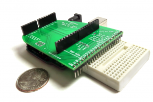
Let’s look at an example of how you could generate a fully functional model for the ST Microelectronics ISM330DHCX Accelerometer using a modern tool named Embedd.
Integrating the ISM330DHCX Accelerometer using Embedd.it
So, how do we move from fragmented vendor documentation to a clean, structured hardware model without spending days building it by hand?
That’s where Embedd.it comes in.
Embedd.it is a modern solution to a decades-old problem. It bridges the gap between outdated datasheets and production-ready firmware by transforming raw hardware descriptions into structured, machine-readable models.
Here’s what makes it different:
- AI-Powered Parsing – Embedd.it uses AI NOT to generate code directly, but to interpret and stabilize vendor documentation, extracting signal names, register maps, timing specs, and more with high accuracy.
- Deterministic Output – All models and generated code are fully traceable. There’s no hallucination, no guesswork. Just clean, consistent, verifiable output.
- Structured Component Models – The result is a digital twin of the component: a structured, reusable hardware model that can be used for code generation, documentation, validation, and simulation.
- Hardware-Ready Integration – The models work seamlessly with your build system and board. You can generate drivers, configuration files, or even run hardware-in-the-loop tests before ever committing to a hand-written line of firmware.
For example, instead of digging through 167 pages of the ISM330DHCX datasheet and manually coding every register interaction, Embedd.it builds a complete, structured model of the component in minutes, ready to plug into your firmware stack.
Let’s take a look at how it works.
Creating the Data Model (Processing the Datasheet)
Writing a driver for the ISM330DHCX from scratch would take at least several days, if not weeks, even for an experienced firmware engineer. If you were trying to decide between several inertial chips, a lot of time could be spent just setting up and testing them.
Instead, we can generate the data model and driver and test the ISM330DHCX in less than an hour. I know it sounds unrealistic, but I’ve done it and found it straightforward.
First, we download the datasheet for our device. As I mentioned earlier, the datasheet for the ISM330DHCX is about 167 pages full of register maps and descriptions. (It’s great reading if you have trouble sleeping at night.)
Instead of manually reading all those pages and trying to wrap our brains around it, we will upload the datasheet to Embedd. If a data model already exists, then we’ll be able to use that data model. Their AI will parse the datasheet and create a model if the model doesn’t exist.
You’ll find that once the datasheet is uploaded and the model is created, we’ll have a configuration appear in the Embedd Explorer as shown below:
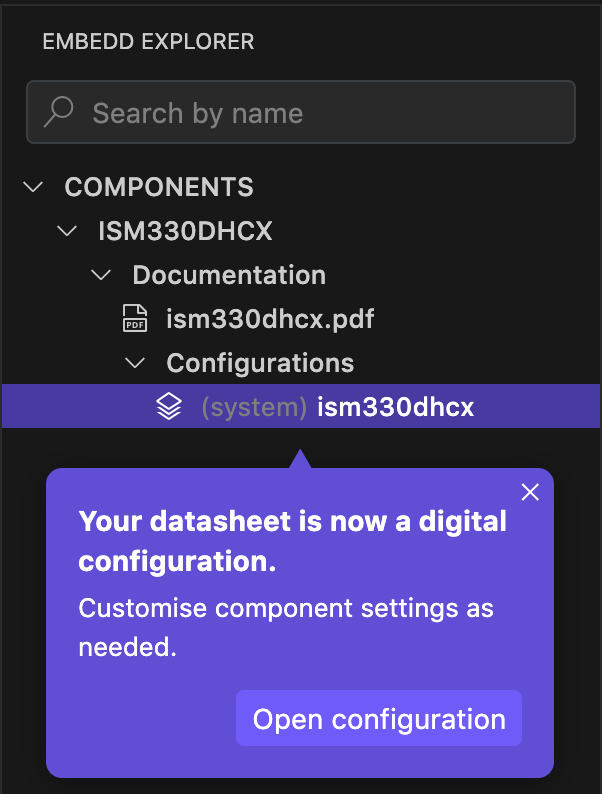
We can create as many configurations for the accelerometer as possible with different settings and operational modes. For testing, we only need one though.
Configuring the Bus Settings
When you open the configuration, you’ll discover several tabs along the top that allow you to configure the device.
The first tab is the general information tab, as shown below:
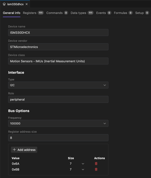
The general information tab provides basic configuration information, such as the device interface (I2C or SPI), the device’s role, and bus options. There are also options to set the I2C device addresses. The defaults are used, but if you have changed the I2C address on the device, you’ll update them here.
A key point to realize is that while the tool has generated the data model automatically, we have complete control over it! If we discover a setting that needs to be changed, an incorrect default, or a register that was missed, we can make those changes in the model.
Configuring the ISM330DHCX Registers
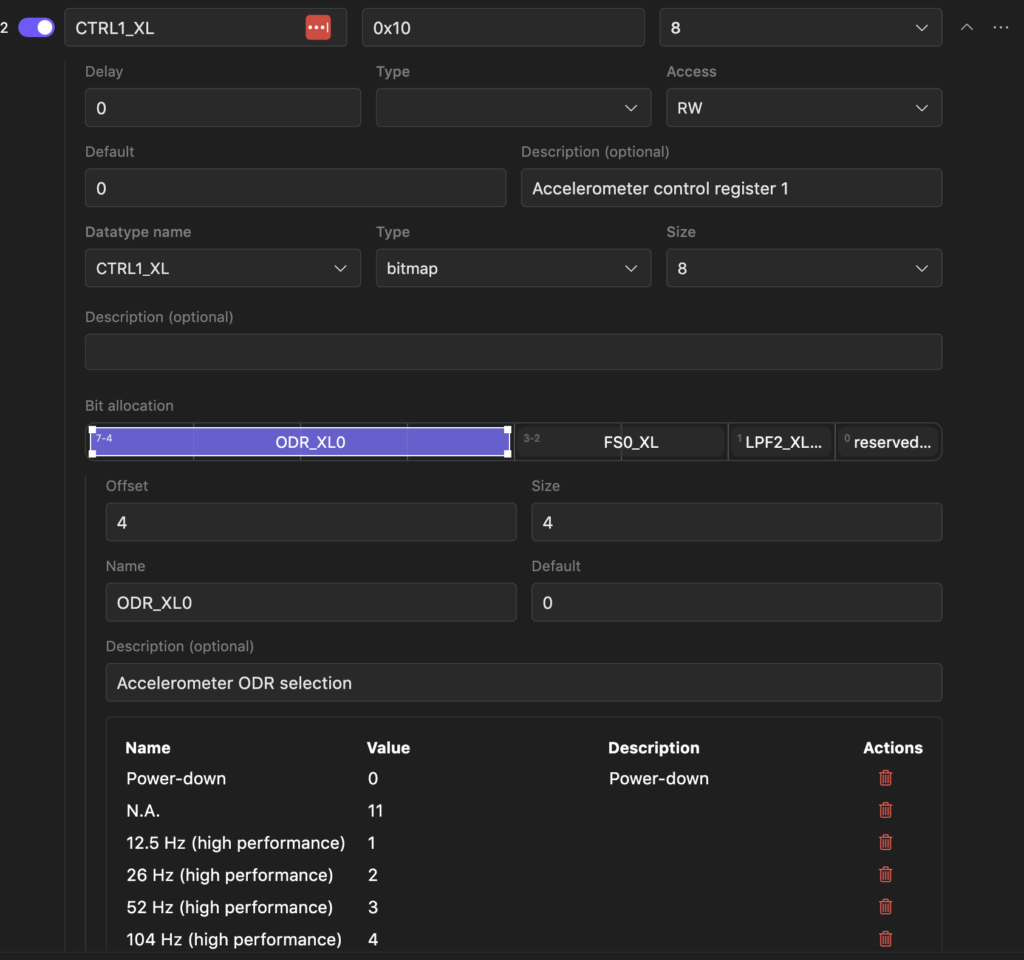
The next tab in the configuration is the Registers tab. It lists every register in the device. You can see in the image below that the ISM330DHCX has 111 registers that can be configured! Not exactly a simple device!
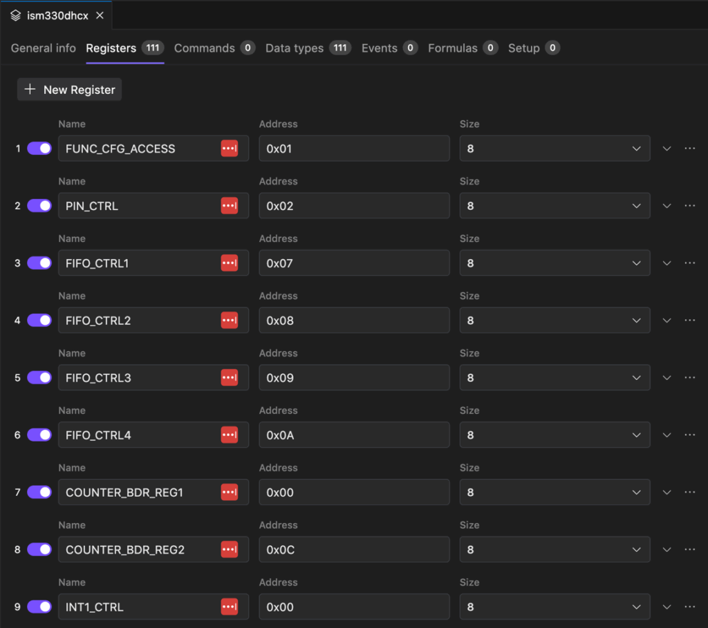
What’s cool though is that we have complete control over these registers. You can review what’s here and dig in deeper. For example, if I wanted to know how to enable the accelerometer, I could go to the control registers and expand them to see the default settings. As you can see below, I can see all the information about the CTRL1_XL register! I can see that it is the Accelerometer control register. I know the bit allocation breakdown. If I click on a specific bit mask, I can see different settings and options!
Formulas and Combined Registers
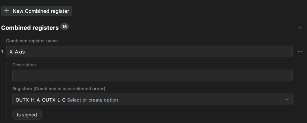
A very powerful feature of the Embedd configuration is the ability to combine registers and create formulas.
For example, the ISM330DHCX has two different registers that hold the X-Axis accelerometer data, OUTX_H_A and OUTX_L_A. One is the high byte, and one is the low byte. We can create a combined register under the Formulas tab that will make the combined value available to the application as shown below:
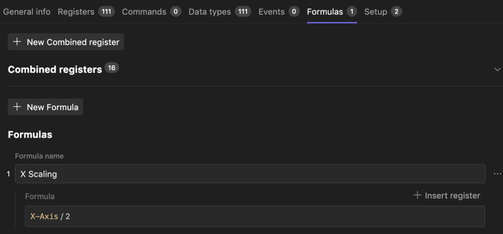
In addition, we can also scale registers or convert them from raw values to scientific values. Let’s say that the X-Axis accelerometer data needed to be scaled by a factor of two. We can add a formula that does this for us, as shown below:
Initializing the ISM330DHCX
The last tab that we will discuss before running the model on hardware is configuring registers at start-up with the values we want them to have. We’ll use the default settings except that we want to set up the CTRL1_XL accelerometer control register to enable the accelerometer.
Under the Setup tab, we can add the CTRL1_XL register as shown below:
Notice that we can see the whole bitmap and control the individual values. We can even see the options for the register and bitmap from the dropdown. I’ve set the accelerometer to sample at 12.5 Hz in this example.
Testing the ISM330DHCX Model
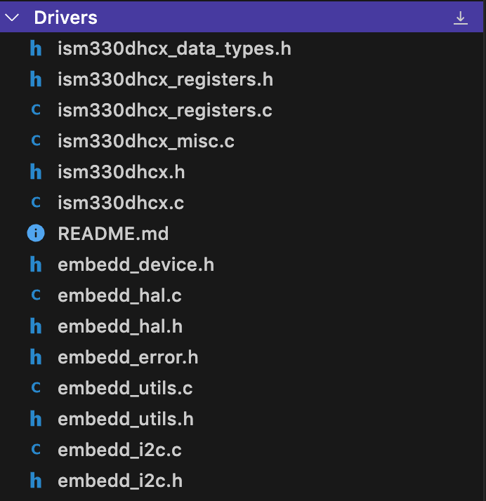
Embedd allows us to use our configuration to Generate Driver or Test configurations. By clicking Generate->Driver I can get a complete C based driver that I can pull into a project as shown below:
For our purposes today, we are going to look at what happens when we use the Generate->Test feature.
If you create a test configuration, you’ll find yourself on a screen like the following:
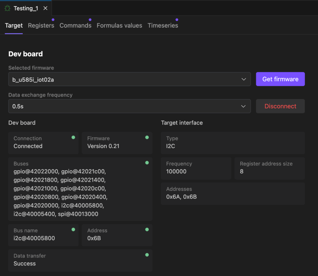
You can see that this screen allows you to:
- Select the target board. In this case, I’m using the B_u585_iot02a development board.
- Download test firmware that you can flash to your development board for testing your device.
- Connect to the development board to pull live data from the device that you are testing.
Next, you can go to the Registers tab to see the live values for any of the registers. Since we are looking at an accelerometer, looking at the live values for the X, Y, and Z axises would be of interest, as shown below:
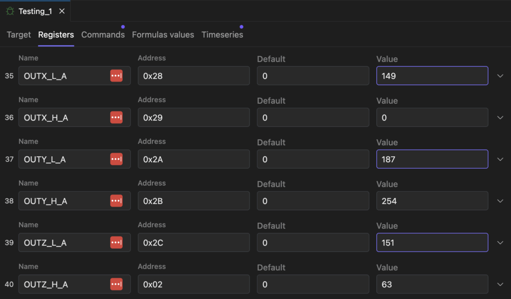
I was able to move the board around and see how the accelerometer values changed with time.
The real cool feature for testing is that there is also a Timeseries tab. Under this tab, you can add charts that graph the value of registers like the OUTX_H_A. However, you can also graph combined registers like the X-Axis register we created as shown below:
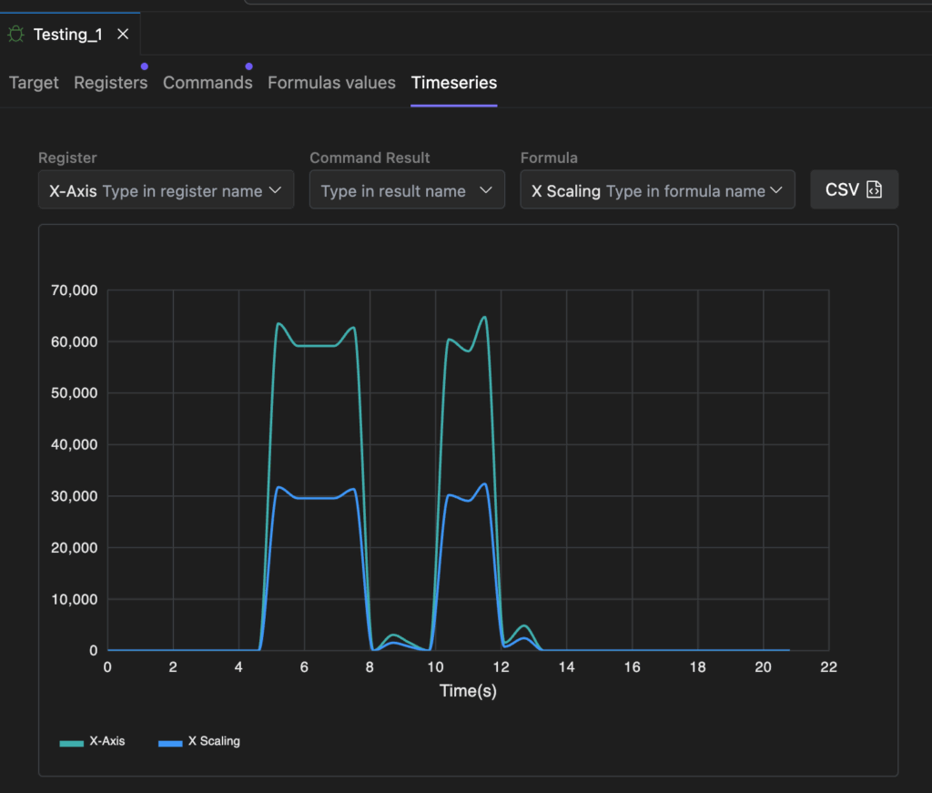
In the image above, you can see that I’m also plotting the X-axis formula, which involves taking the resultant combined register value and dividing it by two!
You can also export the data as a CSV file to analyze it and compare its performance to other devices you may be testing or comparing.
The Bottom Line
Solving hardware integration at the data level, before firmware is even written, enables faster, smarter, and more reliable development. Firmware should be generated from structured truth, not reverse-engineered from scattered PDFs, example code, or tweaked through trial and error.
By shifting our focus upstream to machine-readable component models and deterministic code generation, tools like Embedd.it empower teams to adapt quickly, reduce integration errors, and reclaim time for innovation.
Here are a few next steps you can take to turn your hardware problem into a data problem:
- Select a peripheral you use regularly, such as a pressure sensor, accelerometer, or I/O expander.
- Sign up for a free account at https://embedd.it.
- Upload the datasheet and explore how the tool transforms it into a structured, testable, and code-generatable model.
No driver to write. No SDK to untangle. Just a clean, verifiable component built from the source of truth. Because in the end, there is no hardware, only data.
Struggling to keep your development skills up to date or facing outdated processes that slow down your team, raise costs, and impact product quality?
Here are 4 ways I can help you:
- Embedded Software Academy: Enhance your skills, streamline your processes, and elevate your architecture. Join my academy for on-demand, hands-on workshops and cutting-edge development resources designed to transform your career and keep you ahead of the curve.
- Consulting Services: Get personalized, expert guidance to streamline your development processes, boost efficiency, and achieve your project goals faster. Partner with us to unlock your team's full potential and drive innovation, ensuring your projects success.
- Team Training and Development: Empower your team with the latest best practices in embedded software. Our expert-led training sessions will equip your team with the skills and knowledge to excel, innovate, and drive your projects to success.
- Customized Design Solutions: Get design and development assistance to enhance efficiency, ensure robust testing, and streamline your development pipeline, driving your projects success.
Take action today to upgrade your skills, optimize your team, and achieve success.