How to Write a Zephyr Devicetree with AI
Writing a Zephyr Devicetree with AI is appealing for one reason: doing it by hand is slow and easy to get wrong.
For every signal on the board, you look up which GPIO port and pin it lands on, find the right pinmux option, pick the binding that matches the part, and hand-translate all of it into Devicetree nodes. Transpose a pin number or forget an active-low flag, and the build still passes. The application just doesn’t work as expected, and you spend the afternoon debugging!
AI can automate that work in seconds. Unfortunately, a generic AI model can also hallucinate bindings that don’t exist, invent pins that aren’t on the MCU, or generate nodes that violate Zephyr’s Devicetree rules.
The solution to Zephyr Devicetree with AI isn’t a better prompt. It’s giving the AI the ability to validate its work. By checking the existing Zephyr bindings, cross-referencing device properties, and verifying the generated nodes against the Devicetree schema, AI can produce a Devicetree grounded in the actual Zephyr ecosystem rather than educated guesses. (Which AI seems to just love to do!)
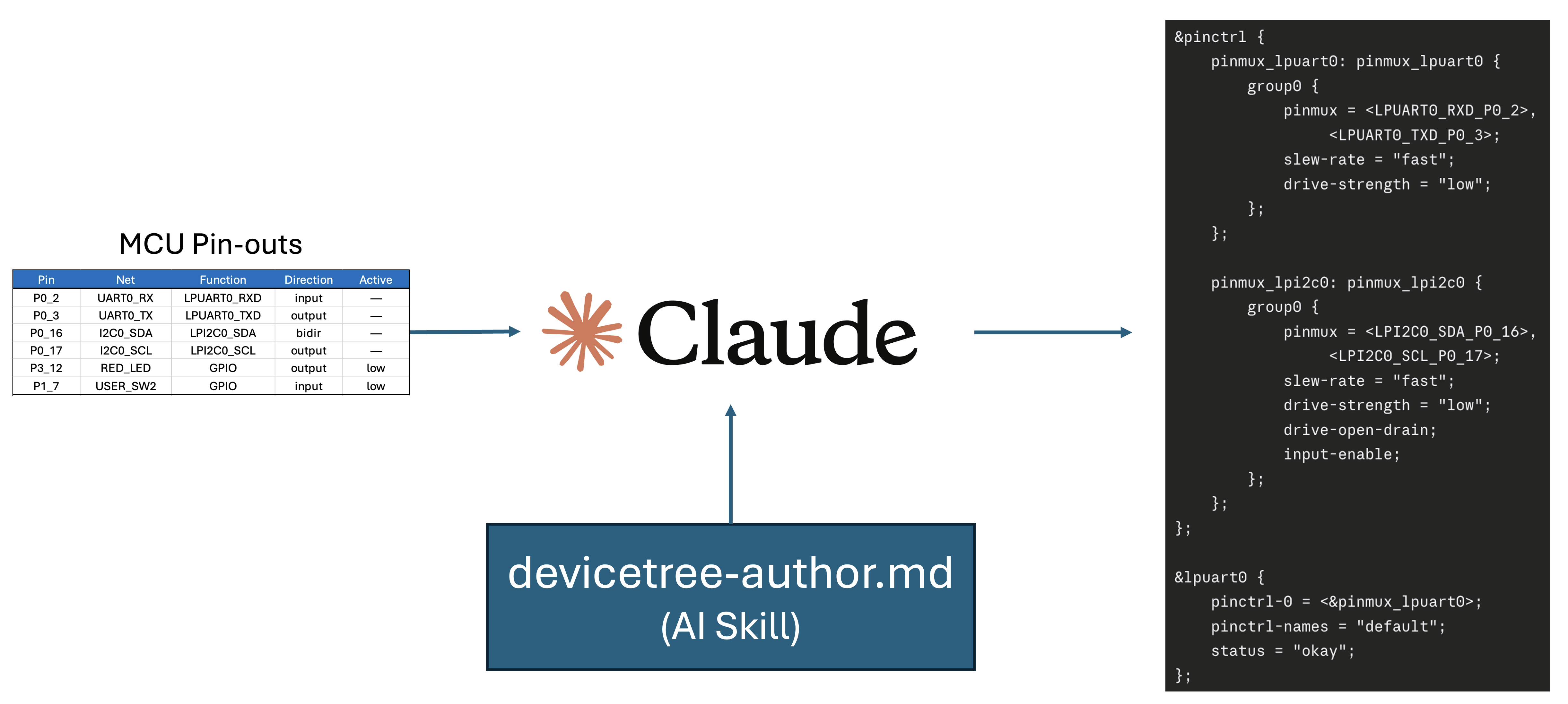
In this post, I’ll start with a simple hardware pinout table that any hardware engineer can build in a spreadsheet. We’ll then use an AI skill to generate a validated Zephyr Devicetree with AI for the NXP FRDM-MCXA156. Along the way, you’ll see how the validation process prevents many of the mistakes that generic AI tools commonly make.
Let’s dig in!
What Is a Zephyr Devicetree, and Why Write It with AI?
A Zephyr Devicetree is a build-time description of your hardware that the build system compiles into C macros. Your application can then access your hardware through those macros in an abstract manner, without exposing hardware details.
The Devicetree is made up of a series of files that contain nodes, aliases, and other hardware configuration information. (We’ll talk more about this later.) Writing the Zephyr Devicetree with AI means generating nodes from a pin map rather than hand-coding them. The work suits AI because it is pattern-heavy and reference-driven rather than creative.
That build-time detail matters. Linux reads a devicetree at boot. Zephyr evaluates it when you compile, so only the drivers and configuration your hardware actually uses end up in the binary. The Devicetree is the single source of truth for what exists on the board and how it is wired.
You may recall from previous posts that three different file types carry the device description. The board’s .dts file is the top-level hardware description for your board. A .dtsi file describes the system-on-chip (SoC) and is included by the board. An overlay extends or overrides the tree without touching the board files, which is how you adapt a stock board to your own hardware. If you want the full tour of that syntax, I covered it in Mastering the Zephyr RTOS Devicetree and Overlays.
Every peripheral is a node; every node has properties, and one property does the heavy lifting: compatible. The compatible string is how Zephyr matches a node to its binding, a YAML (structured text) file that declares which properties the node must have and which driver claims it. Get the compatible wrong, and nothing binds.
Here is why writing your Zephyr Devicetree with AI is good AI work. Every node is a lookup. Which port and pin does this signal use? Which binding matches this part? What address is on this bus? That is mechanical translation, which is error-prone and frankly boring for a human to do. Language models are fast at it. The catch is that the model knows the pattern, not your board. It has never seen your schematic. Feed it a general direction, and it will fill the gaps with confident fiction.
So the workflow does not start with a prompt. It starts with a map of your hardware.
Start with a Pinout Map a Hardware Team Can Build
The right input for AI is not a schematic. It is a simple table of pin, signal, function, and state, the kind of pinout map a hardware team already produces in a spreadsheet. That table tells the AI everything it needs to write correct nodes, and nothing it has to guess.
A spreadsheet beats a PDF schematic here for a practical reason. AI reliably parses a clean table but reads a schematic image poorly. I’ve seen models successfully read PDFs, but it’s never clean, and there are usually several questions that come out of the reading. The result is still having to hand-code some of the Devicetree or dig into the details to help clarify the model’s direction.
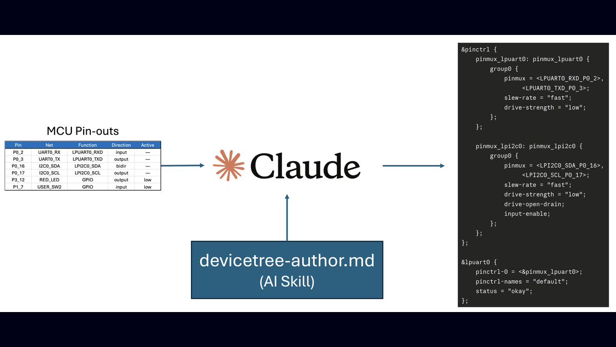
A table also forces the hardware team to commit to a single value per pin, which is exactly the discipline you want before any node is written. Four columns carry the load: the pin, the net or signal name, the peripheral function or mux, and the direction with its active state. For example, check out the simplified table from a weather station project I’m working on with the FRDM-MCXA156:
| Pin | Net | Function | Direction | Active |
|---|---|---|---|---|
P0_2 | UART0_RX | LPUART0_RXD | input | |
P0_3 | UART0_TX | LPUART0_TXD | output | |
P0_16 | I2C0_SDA | LPI2C0_SDA | bidir | |
P0_17 | I2C0_SCL | LPI2C0_SCL | output | |
P3_12 | RED_LED | GPIO | output | low |
P1_7 | USER_SW2 | GPIO | input | low |
Free for Zephyr Developers
Get a Free NXP FRDM-MCXA156 Dev Board
NXP is offering 500 free FRDM-MCXA156 boards to embedded developers exploring Zephyr. Limited to 500 boards or available through December 31, 2026, whichever comes first.
Claim Your Free Board →The active-state column is the one people skip and the one that often causes problems. An LED wired so that the pin sinks current to ground is active-low. Miss that, and your logic runs inverted: the LED you meant to turn on goes dark. The pinout map is where that fact gets recorded once, so the AI and every engineer after it read the same answer.
Ambiguity in the map is a decision, not a default. A row marked TBD, or two rows claiming the same pin, is a question for the hardware team. A good Zephyr Devicetree with AI workflow stops and asks rather than picking one silently. I was recently setting up a new project using my Zephyr AI Skills when the AI validation process failed. The skill identified a conflict that the hardware team had overlooked.
Had AI not been in the loop, we might never have noticed, and we would have had a sensor issue that would have baffled us for days. Instead, the well-crafted skill spotted the issue and brought it to our attention. A simple adjustment and the conflict was gone.
So, with the hardware pin map in hand, you can now let AI write your Devicetree nodes.
How to Write Zephyr Devicetree with AI Nodes
If you want AI to help you with the Devicetree for your board, you shouldn’t just prompt it. You might get lucky and get the results you want, but if you ask for a change, you’re just rolling the dice and crossing your fingers.
The trick to working with Zephyr Devicetree with AI is setting up a skill that encodes a process and the knowledge about the Devicetree so that your AI tool can repeatably, and dare I say, deterministically give you the right results every time.
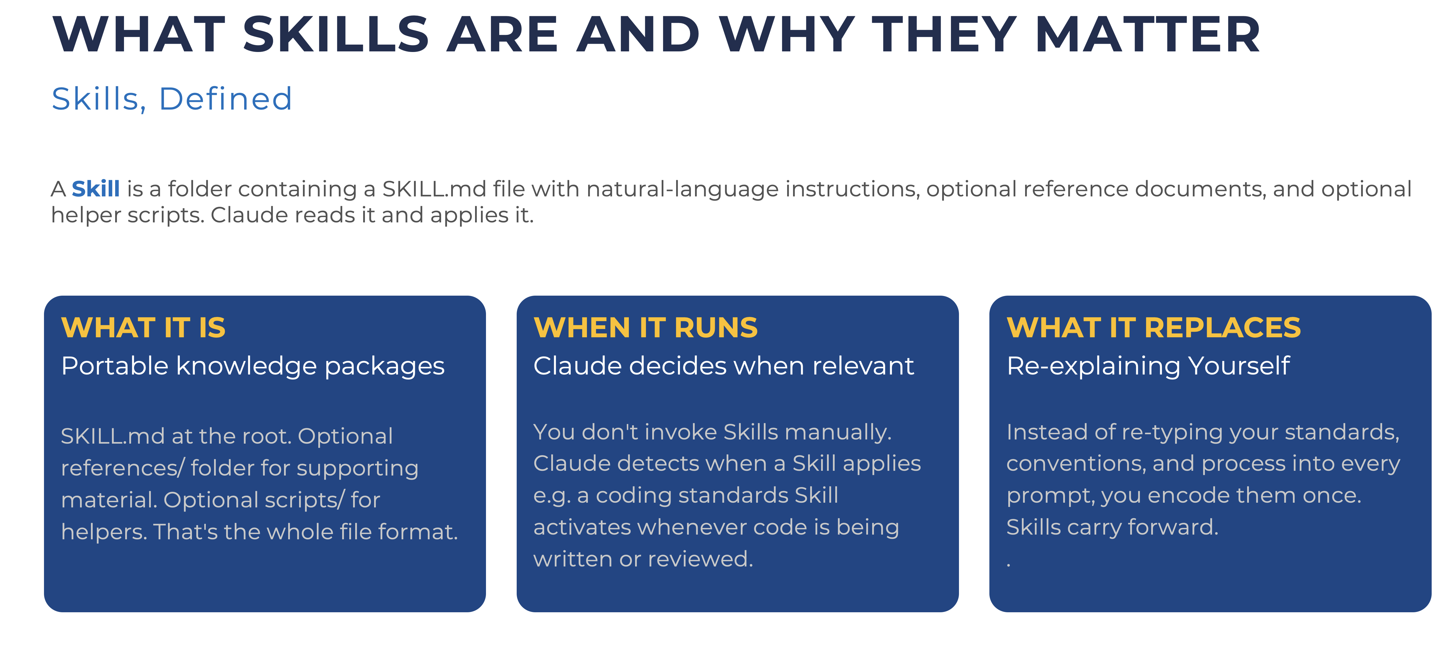
I know that seems counterintuitive. AI isn’t deterministic. Ask for the same thing 10 times, and you’ll get 15 different results! (You get the idea.) I’ve seen it happen, though. I’ve had several hundred engineers take my Build a Custom Zephyr BSP in 3 Hours with AI workshop, who used different hardware and AI tools, yet got the same correct results from a devicetree-author skill!
The trick isn’t about the language you use in your prompt or skill; it’s about writing skills that self-validate.
Writing a Zephyr Devicetree with AI Skill that Self Validates
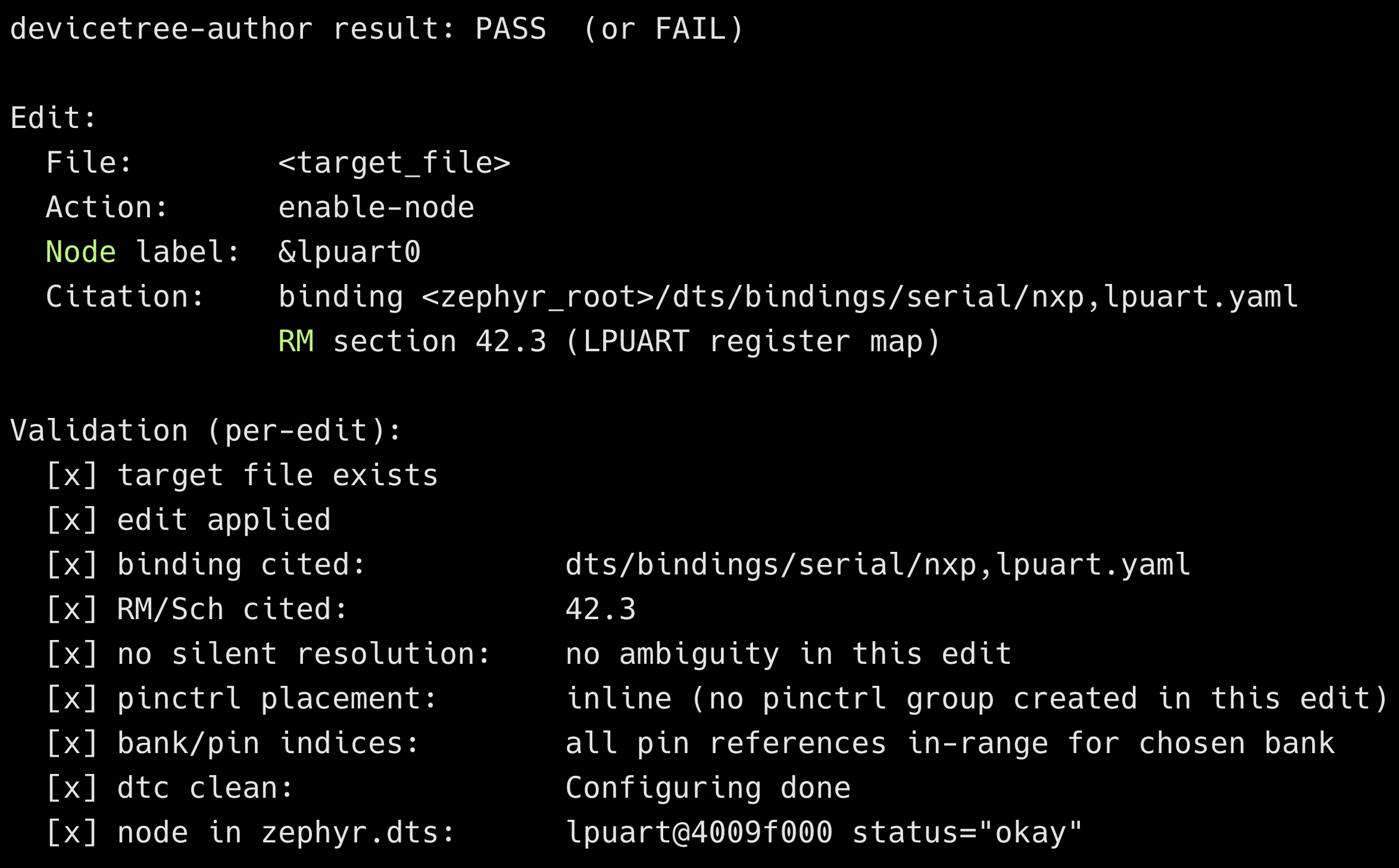
For a Devicetree skill, we want a skill that adds or modifies Devicetree nodes in a Zephyr .dts or .overlay file. We want it to cite the binding YAML for every node and the SoC’s reference manual section for every peripheral or pin reference. Then we want it to validate that the Devicetree Compiler (dtc) accepts the results.
The process of writing a self-validating skill that meets those requirements is straightforward. Here’s what the process looks like:
- Define the skill inputs. What inputs are needed by the skill to be successful? It might be a row in a spreadsheet, a target file path,
board_target, etc. - The procedure to follow. This is a step by step procedure that you would follow if you were writing the devicetree. For example, you might include:
- Read the current devicetree files
- Show the user the section to be edited
- Identify the binding YAML for the new compatible string
- Halt on ambiguity
- Construct and edit
- Run
dtcvalidation - Verify the new nodes
- Final edit and production audit
- A self-validation protocol. What checks are performed on the output to validate that they are correct.
- The output format. What does the user see after the skill runs? The devicetree-author skill I put together does the following for output:
- Miscellaneous. Anything extra that should be discussed. Examples, retries, when the skill should stop and ask questions, etc.
Once you’ve created your own skill or downloaded mine, you can now feed it your spreadsheet!
Free for Embedded Bytes Subscribers
Download the Zephyr AI Skills
Five self-validating skills that turn AI into a real Zephyr BSP teammate: devicetree-author, kconfig-tuner, build-doctor, and more. Cut BSP bring-up from days to minutes with prompts that cite the actual Zephyr bindings.
Get the Skills →How do I Write GPIO and USART Nodes for a Zephyr Devicetree with AI?
Now that you are armed with a reusable Devicetree skill, we can set up our FRDM-MCXA156 with the settings in the table from earlier in this post. To accomplish this task, we can proceed in two ways.
First, you can prompt your favorite AI tool with the following:
&lpuart0 in weather/app/boards/frdm_mcxa156_weather_revA.overlay. Set status = "okay", current-speed = 115200, pinctrl-0 = <&pinmux_lpuart0>, and pinctrl-names = "default". Cite the LPUART binding YAML and the NXP MCXA156 RM section.The devicetree-author skill will then:
- Read the existing overlay
- Locate the binding at
dts/bindings/serial/nxp,lpuart.yaml - Apply the edit with the binding path and RM section in a comment
- Self-validate that the target file exists, the edit is applied, and the binding is on disk
Now you might be wondering why cite the binding and the RM? Two reasons. First, citations let you verify the AI’s work without trusting its judgment. The binding YAML is a real file on disk; either it exists and matches what the skill claimed, or it does not. Second, citations make the diff durable. A reviewer six months from now sees not only what changed but why that property has the value it does.
Second, you can prompt your favorite AI tool to iterate over your spreadsheet as follows:
weather-station-pinouts.xls. Enable peripherals associated with the pin mux. Prompt the user for specific configuration settings that are not defined, like serial baud rates. Save an audit trail for each entry and cite the binding YAML and NXP MCXA156 RM section.That’s it! Your favorite AI would now iterate through your spreadsheet, creating your devicetree overlay and modifying your board’s .dts files as appropriate.
I will point out that this just sets up your Devicetree. You may need to tune your Kconfig settings based on that Devicetree. That’s exactly what the kconfig-tuner skill is for! (But we’ll have to save that one for another time.)
Your Next Steps for Zephyr Devicetree with AI
It’s tempting to just jump into an AI prompt and ask it to develop your Devicetree for you. That would be a mistake. AI is not deterministic, unless you create a self-validating skill that tests its own outputs and does its own research to make sure it’s not making stuff up!
In this post, I showed you how to write a Zephyr Devicetree with AI using skills. The ideas are interesting, but they will stay abstract unless you put them into practice.
Here are a few ways to go deeper:
- Build a pinout map for the FRDM-MCXA156 on your bench.
- Run my Zephyr AI Skills.
- Write your own AI Skills to help you with your embedded systems development.
Don’t let the Devicetree get in your way of adopting Zephyr RTOS or slow your development down. Write your Zephyr Devicetree with AI!
Want embedded engineering insights like this delivered to your inbox? Sign up for my Embedded Bytes newsletter to get the latest posts, insights, and hands-on tips delivered straight to your inbox.
Additional Resources
- Download: Zephyr RTOS AI Skills
- Blog: Introduction to the NXP MCX N FRDM Board
- Blog: Getting Started with Zephyr RTOS
- Blog: How to Configure Zephyr RTOS: A Practical Guide to West, Kconfig, proj.conf
- Blog: FreeRTOS to Zephyr Migration: A Step-by-Step Guide for Embedded Developers
- Blog: Mastering the Zephyr RTOS Devicetree and Overlays
- Blog: Zephyr RTOS Sensor API: Unlock On-Board Temperature Sensing
- Blog: Zephyr RTOS: Porting Apps Across Different Boards
- Blog: Zephyr Custom Board: Create One in Under an Hour
- Free Training: Getting Started with MCUXpresso for Visual Studio Code
- Free Webinar: Getting Started with the MCUXpresso SDK for NXP MCUs
Frequently Asked Questions
What is the difference between a devicetree overlay and a binding?
An overlay is a fragment that extends or overrides the devicetree for your board or application. A binding is the YAML schema that defines what a node of a given compatible may contain and which driver claims it. The overlay describes your hardware; the binding describes the rules that hardware description must follow.
Can AI write a Zephyr Devicetree correctly?
Yes, for the mechanical translation, when you give it a structured pinout map and the target board. It still makes binding, bus, and pin mistakes, so treat its output as a draft you verify with a build, not a finished file.
What is pinctrl in Zephyr, and where should it live?
Pinctrl is how Zephyr assigns peripheral functions to physical pins and sets electrical properties like drive strength and slew rate. Put pin groups in the board’s <board>-pinctrl.dtsi file and reference them with pinctrl-0 and pinctrl-names, so the pin muxing stays organized as the board grows.
How do I create a custom devicetree overlay for my board?
Add a .overlay file under your application’s boards/ directory, named for the board target. Zephyr applies it on top of the board’s .dts at build time. Use &label blocks to enable or extend nodes that already exist in the base tree.
How do I add a sensor to a Zephyr Devicetree with AI?
Give the AI the sensor part number, its bus, and its address, and ask it to add a child node under the bus parent with the matching compatible. Confirm the cited binding YAML exists, then enable the driver in Kconfig.
Why does my Zephyr build pass but the hardware does nothing?
Usually a devicetree value that compiles but is wrong: an inverted active-state flag, a pin in the wrong GPIO bank, or a node missing its label so DT_NODELABEL never resolves. Read build/zephyr/zephyr.dts and confirm the node matches the board.
Struggling to keep your development skills up to date or facing outdated processes that slow down your team, raise costs, and impact product quality?
Here are 4 ways I can help you:
- Embedded Software Academy: Enhance your skills, streamline your processes, and elevate your architecture. Join my academy for on-demand, hands-on workshops and cutting-edge development resources designed to transform your career and keep you ahead of the curve.
- Consulting Services: Get personalized, expert guidance to streamline your development processes, boost efficiency, and achieve your project goals faster. Partner with us to unlock your team's full potential and drive innovation, ensuring your projects success.
- Team Training and Development: Empower your team with the latest best practices in embedded software. Our expert-led training sessions will equip your team with the skills and knowledge to excel, innovate, and drive your projects to success.
- Customized Design Solutions: Get design and development assistance to enhance efficiency, ensure robust testing, and streamline your development pipeline, driving your projects success.
Take action today to upgrade your skills, optimize your team, and achieve success.